Simple views of two fieldbus segments are shown below. One segment uses a redundant H1 card that requires external fieldbus power and the other uses a redundant H1 with Integrated Power card.
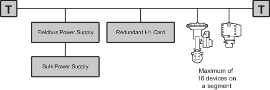
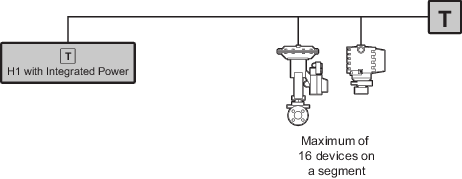
In this document, the wire or cable between the two terminators is referred to as the trunk, and any connections that branch off from the trunk are referred to as spurs. In the image above, the fieldbus power supply, the H1 host, and field devices, are shown connected between the terminators. Any of these three devices can be connected as spurs between the terminators or as spurs beyond the main trunk.
There are several ways to design a fieldbus segment topology: point-to-point, chicken-foot, daisy chain, trunk with spurs, and tree. This document focuses on a trunk with spurs topology and takes into account the different types of wiring that are available for fieldbus segments, wire distribution issues, length restrictions, and power issues.
Daisy chaining from device to device is not recommended.
To minimize the possibility of communication problems, Emerson recommends that the trunk be a continuous run of the same type of cable. Fieldbus Type A cable is recommended. Devices can be connected anywhere along the trunk, following the rules associated with spur length.
Fieldbus was designed to operate properly on a variety of existing plant wiring and it is possible that your specific application could operate on existing runs of instrument cable. However, as the cable length and number of devices increase, it is possible to exceed the reliable operating margins of the fieldbus segment if you do not keep the application-specific requirements discussed in this document in mind when you design the segment.