- Securely attach the Field Barrier at the desired location.
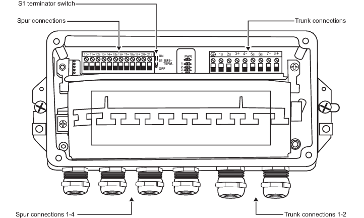
- For the trunk segment connection: connect the positive (+) segment wire to the positive, connect the negative (-) segment wire to the negative, and connect the segment shield (S) to the S.
- Remove the shorting jumpers (1B, 2B) so that the trunk (S) shields are isolated from, not connected to the Field Barrier case.
- For each device connection: connect the positive (+) spur wire to the positive, connect the negative (-) spur wire to the negative, and connect the shield wire (S) to the S.
- The spur (S) shields must be connected to the Field Barrier case and isolated at the device in the field. The best way to ground the output shields at the barrier is with a mechanical connection through a metal gland or bar at the barrier.
- If this Field Barrier is at the end of the segment, the terminator switch S1 should be in the On position. If this is not the end of the segment, ensure that the terminator switch S1 is in the Off position.
- If the segment continues and connects to another Field Barrier, continue the trunk segment by connecting the trunk out connections to the next Field Barrier and proceed with steps 3, 4, and 5.
- Ensure that the shorting jumpers (1B, 2B) are removed on all Field Barriers, so that the trunk (S) shields are isolated from, not connected to, the Field Barrier case.
- If this Field Barrier is the end of the segment, ensure that the terminator switch S1 is in the On position.
- Verify the installation with the segment checkout procedure.