Control strategies in the DeltaV system are configured in modules. A module, which is the smallest logical control entity in the system, contains algorithms, conditions, alarms, displays, historical information, and other characteristics that define the process equipment. Algorithms are the logical steps that define how a module behaves. The DeltaV system provides control, equipment, and unit modules.
Generally, a control module contains one uniquely tagged control entity, such as a control loop or motor, with its associated logic. Defining a module around a single field device and its related control logic makes it easy to create, download, operate, debug, and take a single module out of service without affecting other modules.
Equipment modules coordinate the operation of control modules and other equipment modules that work together to control related equipment. The algorithm for the containing equipment module manages the operation of the contained modules.
Unit modules can be used in non-batch applications to group control modules and equipment modules for alarm management purposes. For example, alarms for a specific unit, such as a boiler, can be combined. All control and equipment modules associated with the unit will be contained within the unit module.
Function blocks are building blocks for creating the continuous and discrete algorithms that perform the control or monitoring for the process. The DeltaV Library contains function block templates for analog control (bias/gain, lead/lag, PID, etc.), Logical, I/O (analog and discrete input/output), and other basic functions. Each function block contains parameters that can be modified to customize the algorithm. Algorithms range from simple input conversions to complex control strategies. Function blocks can be combined into composite function blocks to build complex algorithms.
In addition to Function Block algorithms, the DeltaV system supports Sequential Function Charts (SFCs) as well as Command-driven and State-driven algorithms for control tasks requiring sequencing strategies.
Parameters are the user-defined data used within a module's algorithm to perform its calculations and logic. Parameters can be described by the type of information they provide, such as input or output. Tables listing the parameters and their properties are included in Books Online.
The DeltaV system includes a library of pre-engineered module templates with basic characteristics. You can customize these library modules or create your own modules from scratch. You can then add your customized modules to the library, making them available for reuse in the development of your control strategy.
Modules that work closely together to perform a specific process control function are typically grouped in an area. An area is a logical division of a plant. Areas typically represent plant locations or main processing functions. The configuration engineer determines how to logically divide the plant into areas.
Nodes are physical pieces of equipment on the control network, such as a controller or a workstation. You control your process by downloading modules to the controller nodes. The configuration tells the node how to act and what information to receive or save from the process.
Device Tags represent the instruments, valves, and other field devices. A Device Signal Tag consists of a specific signal from a device.
Alarms alert the operator that an event has occurred. (Alarms are assigned to modules.) Typically, you want the operator to perform some action and respond to the alarm. Alarms can be both visible and audible.
The database contains configuration information and lets you make off-line changes without affecting the process. Online control algorithm monitoring and modification are also available.
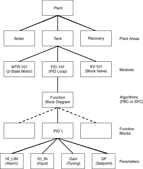
The following diagram shows an example of a DeltaV system hierarchical structure.