Installation notes
- The following information applies only to part number KJ1503X1-BD1. For other DeltaV redundancy modules with similar characteristics, you can obtain documentation from Emerson Global Support Center at 800-833-8314.
- Install this redundancy module on a horizontally oriented DIN rail with the label text right-side up.
- Keep the following installation clearances: 40 mm on top, 20 mm on the bottom, 5 mm on the left and right sides when the device is loaded permanently with more than 50% of the rated output current. Increase the side clearance to 15 mm if the adjacent device is a heat source such as a power supply.
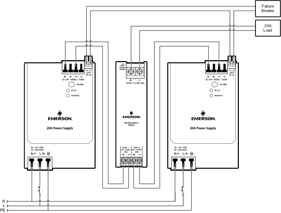
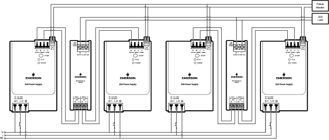
- This redundancy module can be used in one-to-one and n-to-one redundant systems. Use diodes or other switching arrangements to isolate the redundant power supply outputs from each other.
- Connect the two input channels to the 100-240 VAC to 24 VDC 20 A DeltaV Bulk Power Supply for redundant applications.
Specifications
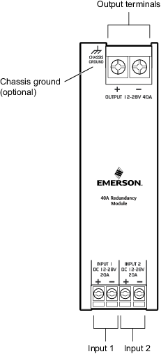
Terminals and wiring
Screw terminals with IP20 finger safe construction are used. The terminals are suitable for field and factory wiring. Use wire that complies with local codes and regulations.
| Wire type | Input screw terminals | Output screw terminals |
|---|---|---|
|
Solid wire |
Maximum wire gauge: 6 mm2; 10 AWG |
Maximum wire gauge: 16 mm2; 6 AWG |
|
Recommended tightening torque: 0.8 N · m; 7 lb. · in. |
Recommended tightening torque: 1.2 N · m; 10.6 lb. · in. |
|
|
Stranded wire |
Maximum wire gauge: 4 mm2; 12 AWG |
Maximum wire gauge: 10 mm2; 8 AWG |
|
Recommended tightening torque: 0.8 N · m; 7 lb. · in. |
Recommended tightening torque: 1.2 N · m; 10.6 lb. · in. |