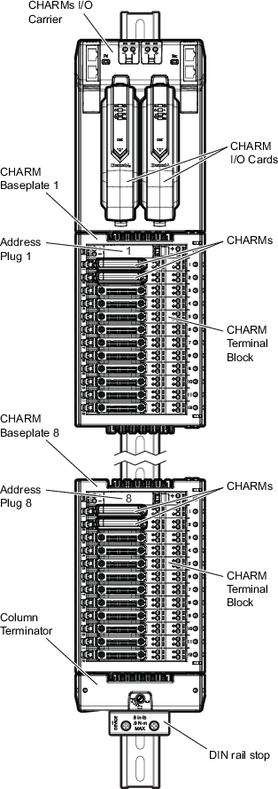
CHARMs I/O consists of:
- CHARM I/O Cards (CIOC)
- Simplex or redundant cards that process CHARMs I/O signals to and from the controller. A CIOC can support up to 96 conventional and Intrinsically Safe (I.S.) CHARMs. The maximum number of CHARMs (96) are organized in eight banks of 12 CHARMs. Each bank of 12 CHARMs is held by a CHARM Baseplate.
- CHARM I/O Carriers
- The DIN rail-mounted carrier that holds simplex or redundant CIOCs. The CHARM I/O Carriers provide redundant 24 VDC power to the CIOC and bussed power to the field circuits. Ethernet cascade ports (primary and secondary) on the CIOC allow up to 16 CIOCs to be connected together without wiring back to a central switch.
- CHARMs
- Single I/O channels that plug into CHARM Terminal Blocks on a CHARM Baseplate. The DeltaV system supports conventional analog input and output CHARMs, conventional discrete input and output CHARMs, and conventional RTD and Thermocouple input CHARMs as well as I.S. analog input and output CHARMs and I.S. discrete input and output CHARMs.
- CHARM Terminal Blocks
- Provide the keying and field wiring for the CHARMs. There are several types of CHARM terminal blocks: CHARM Terminal Block, CHARM Fused Injected Power Terminal Block, CHARM Relay Output Terminal Block, and I.S. CHARM Terminal Block.
- CHARM Baseplates
- The DIN rail-mounted vertical carrier that holds a bank of 12 CHARMs and CHARM Terminals and an Address Plug and Address Plug Terminal. Address terminals installed on the non-I.S. baseplates have connectors for injecting field power. The I.S. CHARM Baseplate holds 12 I.S. CHARMs and I.S. CHARM Terminals, an Address Plug and I.S. Address Plug Terminal. The I.S. Address Plug Terminal does not receive injected field power.
- Address Plugs
- Determine the address of the CHARM Baseplates and the CHARMs installed on the baseplate. An Address Plug plugs into a CHARM Address Terminal on the CHARM baseplate.
- Column Terminator
- Attaches to the DIN rail and the last CHARM baseplate to terminate the redundant busses.
- DIN Rail Stop
- Vibration may cause the baseplates to slip down on the DIN rail. The DIN Rail Stop installs after the last baseplate to keep the hardware in place on the DIN Rail.
- CHARM Column Extenders and cables
- When CHARM Baseplates in a 96 CHARM system are installed on multiple DIN rails, CHARM Column Extenders and cables are used to extend redundant power and communication busses to the baseplates. The bottom column extender can be connected to CIOC carriers or to baseplates depending upon the physical location of the carrier and the baseplate. The top column extender can be connected to baseplates only. CHARM Column Extenders are not shown in the following image.
The DeltaV S-series and CHARMs Hardware Installation manual explains how to install CHARMs hardware.