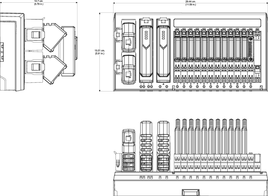
| Number of scanner modules per carrier
|
One for simplex; two for redundancy
|
| IOPs supported
|
I/O Block IOP
- Star Ethernet
topology: 1 IOP for simplex; 2 IOPs for redundancy
- Ring Ethernet
topology: 2 IOPs
|
| CHARM terminal blocks supported
|
- Standard Terminal
Block
- Fused
Injected-Power Terminal Block
- 3-wire DI Fused
Injected-Power Terminal Block
- 3-wire AI Fused
Injected-Power Terminal Block
- Relay Output
Terminal Block
- Thermocouple/mV
Terminal Block
- LS DVC Terminal
Block
- LS Redundant
Terminal Block
- LS Redundant DTA
Fused Injected-Power Relay Terminal Block
- LS Redundant DTA
Relay Terminal Block
- LS Redundant ETA
Relay Terminal Block
- LS Redundant DVC
Terminal Block
|
| Power connections
|
Four screw cage terminals for redundant
connection of ± 24 VDC power: 0.32-2.5 mm2 (22-14 AWG)
|
| Shield connections
|
One screw cage terminal and two for cable
shield grounding: 0.32-2.5 mm2 (22-14 AWG)
|
| Wire strip length
|
7-9 mm (0.28-0.36 in.)
|
|
|
0.32-2.5 mm (22-14 AWG)
|
| Total bussed power
|
250 VAC maximum at 10 A maximum
|
| Bussed power per CHARM slot
|
250 VAC maximum at 2 A maximum
|
| Mounting
|
Latches to horizontal T-type DIN rail
|
| Operating temperature
|
-40 to 70 °C
|
| Storage temperature
|
-40 to 85 °C
|
| Relative humidity
|
5 to 95%, non-condensing
|
| Protection from airborne contaminants
|
ISA-S71.04-1985 Airborne Contaminants Class
G3 conformal coating
|
| Shock
|
10 g half-sine wave for 11 ms
|
| Vibration
|
1 mm peak to peak from 2 to 13.2 Hz; 0.7 g
from 13.2 to 150 Hz
|
| Ingress protection class
|
IP20
|