|
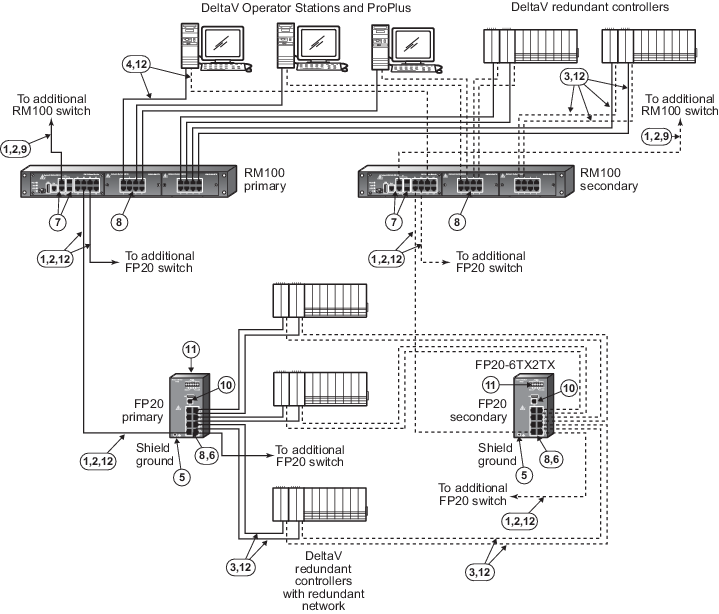
100 m (max) straight-through or crossover
cable. Cat. 5(e) Screened Twisted Pair cable is required between switches.
|

|
To prevent ground loops, build this cable
assembly with a shielded, metal-enclosed RJ45 connector on one end and an
isolated, plastic-enclosed RJ45 connector on the other end. The metal connector
end of this cable assembly/link can be placed on either switch.
|

|
100 m (max) straight-through or crossover
cable. The shield on the controller’s RJ45 connector connects only to a Faraday
cage in the controller; not to the controller’s DC ground. Therefore, the RJ45
connectors are floating and the single point of ground is made at the switch to
which the controller is connected. Build this cable assembly with a shielded,
metal-enclosed RJ45 connector on both ends.
|

|
100 m (max) straight-through or crossover
cable. To prevent ground loops, build this cable assembly with a shielded,
metal-enclosed RJ45 connector on one end and an isolated, plastic-enclosed RJ45
connector on the other end. The metal connector end of this cable assembly/link
must be placed on the switch and not on the PC.
|

|
Use a ring tongue terminal to connect the
ground screw of the switch to a suitable shield ground. This connection
provides a ground for the twisted pair Ethernet shielded connectors.
|

|
The type of ports on this switch are
determined by the switch part number. In this example, all FP20 switches have 8
10/100mb/s twisted pair ports and any number of them can be used for uplinks to
other switches. Other uplink port types are available in fixed hardware
configurations. SFP ports are not available on this switch and this switch has
no gigabit capable ports.
|

|
This switch has two fixed 10/100/1000mb/s
uplink ports and two SFP uplink ports. The SFP ports can be fitted with
optional fiber-optic SFP transceivers for long distance communications. Only
two uplinks can be active at a time in any combination of twisted pair and SFP.
Refer to the ordering information for the available SFP transceivers.
|

|
All twisted pair ports are configured to
autosense speed, autonegotiate duplex, and autodetect polarity. Do not
hard-configure speed or duplex on the twisted pair switch ports or duplex
mismatches, which create communications failures, could occur. Always allow the
switch to autosense speed and autonegotiate duplex. All unused ports on the
switch can be deactivated (locked down) by the Network Device Command Center
(NDCC) after all initial connections are made to the switch. If additional
controllers or workstations need to be connected to unused ports after the
initial lock down, an additional software command from the NDCC is required to
unlock the ports. After the final connections are made, the lock down command
should be reissued to the switch to lock down any remaining unused ports. Once
the ports are in a lock down state, only the original device can communicate on
its original port.
|

|
If more than one RM100 switch is required
to increase port count in an area, use any of the gigabit uplink ports for the
switch-to-switch connection to provide ample performance headroom on these
aggregating links. 100mb/s links can also be used for this purpose but normally
these links are reserved for single devices on the edge of the network such as
controllers and workstations that require much less bandwidth than
switch-to-switch links.
|

|
The serial port is not required for process
communications; it is used only for occasional out-of-band switch setup and
management.
|

|
This connector is used for a +24VDC power
supply input and relay contacts.
|

|
This is a 10/100mb/s twisted pair link.
|