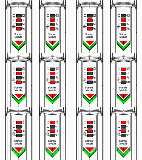
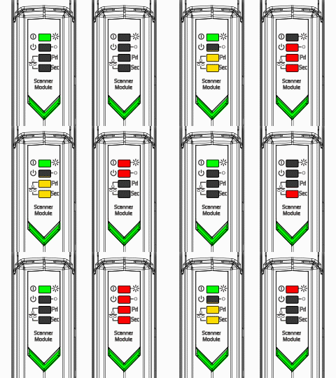
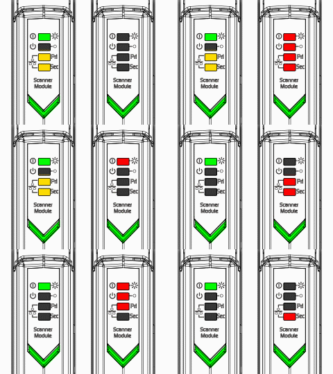
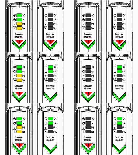
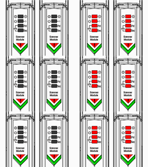
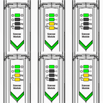
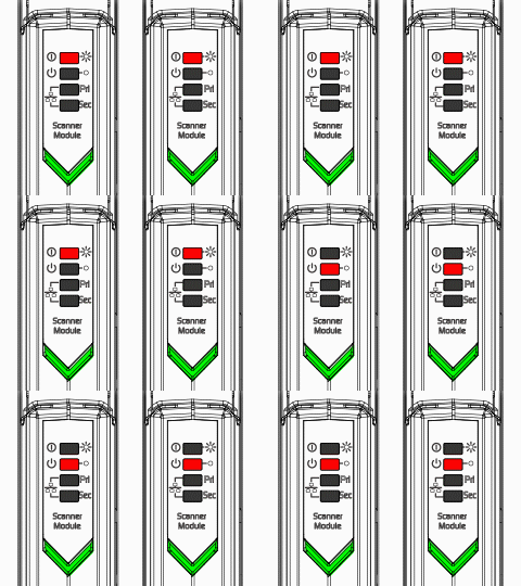
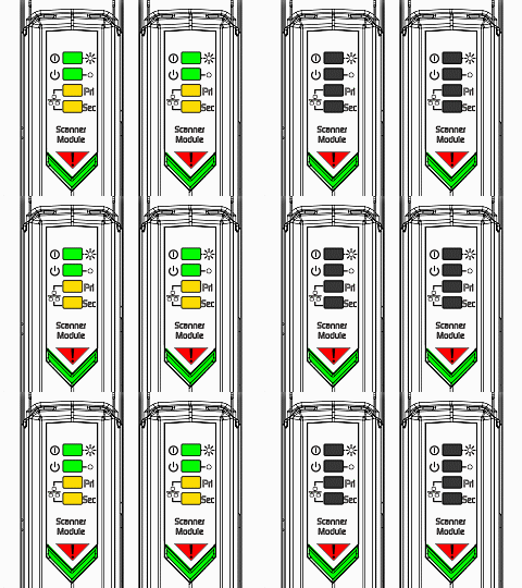
The CHARM Scanner Module has four tri-color LEDs: Active, Standby, COM-A, and COM-B.
The LED behaviors indicate the following conditions for CHARM I/O Scanner Modules installed on a CHARM I/O Gateway:
The LED behaviors indicate the following conditions for CHARM I/O Scanner Modules installed on a CHARM I/O Block:
The LEDs display the following startup sequence when CHARM I/O Scanner Modules are installed on a CHARM I/O Block or Gateway. Some parts of the sequence last longer on the CHARM I/O Gateway.
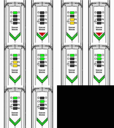
The following two tables show the LED behaviors of CHARM Scanner Modules installed on CHARM I/O Gateways and CHARM I/O Blocks.
Animated illustrations of the LED behaviors are available only in HTML help files, and only on non-DeltaV machines and DeltaV machines that are part of a workgroup. If you are viewing this topic in PDF form, or on a DeltaV machine that is part of a domain, the LED Behavior columns in the following tables display only static images of the LEDs. If you have Guardian support, you can view an HTML help version of this topic on the Guardian Web site.