| Item | Specification |
|---|---|
| Input voltage | 100 - 240 VAC |
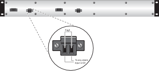
| Alarm contacts | Normally closed. Changes to Open if: |
| Input current | 0.5 - 0.3 A |
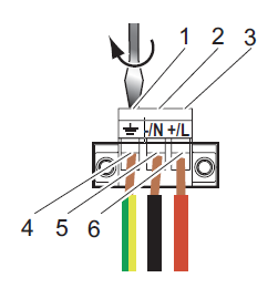


Complete the following steps to connect power to the RM1040 Smart Switch.
- Remove the terminal block from the RM1040 Smart Switch.
- Connect the protective conductor to the protective conductor terminal.
- Connect the positive terminal of the supply voltage to +/L.
- Connect the negative terminal of the supply voltage to -/N.
- If the neutral conductor or the minus terminal of the supply voltage is not grounded, install a suitable fuse in the input line.