DeltaV Smart Switches overview

100 Mbit Media Converters and Dual Media Converter Carrier

Specifications

The DeltaV system supports the 100 Mbit 1-Port Single-Mode Media Converter, the 100 Mbit 1-Port Multimode Media Converter, and the 100 Mbit 2-Port SFP Media Converter, referred to inclusively in this document as the 100 Mbit Media Converters. The 100 Mbit Media Converters convert fiber-optic signals to copper-based signals and copper-based signals to fiber-optic signals. The 100 Mbit Media Converters require the Dual Media Converter Carrier, which mounts on a horizontal DIN rail and accommodates two 100 Mbit Media Converters. The 100 Mbit Media Converters include LEDs that indicate power and connection status.

The 100 Mbit Media Converters primarily provide fiber port connection to the CIOC and the CSLS; however, they can be used for all Control Network applications. The 100 Mbit 1-Port Single-Mode Media Converter and the 100 Mbit 1-Port Multimode Media Converter can be installed in Zone 2 and are suitable for connection to Zone 1 components over the fiber port. Refer to the Installing Your DeltaV Zone 1 Intrinsically Safe Hardware manual in Books Online for information on connecting to the DeltaV Intrinsically Safe system.

Table: 100 Mbit Media Converter Specifications
Item Specification
Power requirement
  • 100 Mbit One-Port Media Converters
    • +24 VDC ±20% at 100 mA maximum
  • 100 Mbit SFP Media Converter
    • +24 VDC ±20% at 150 mA maximum
Copper-wire port One 10/100 BASE-TX port with RJ45 connector, capable of half and full duplex operation
Fiber-optic ports
  • 100 Mbit 1-Port Single-Mode Media Converter
    • One 100 BASE-FX single-mode port with LC connector, full duplex; 1310 nm wavelength; 15 km nominal transmission distance
  • 100 Mbit 1-Port Multimode Media Converter
    • One 100 BASE-FX multimode port with LC connector, full duplex; 1310 nm wavelength; 2 km nominal transmission distance
  • 100 Mbit 2-Port SFP Media Converter
    • Two SFP cages to be used with 100 BASE-FX SFP modules
Fiber-optic link budget
  • 100 Mbit 1-Port Single-Mode Media Converter
    • With 9/125 micron single-mode fiber cable
      • Minimum transmit power: -15 dBm
      • Maximum receive sensitivity: -30 dBm
      • Maximum attenuation: 15 dB
      • Maximum input power: -8 dBm
  • 100 Mbit 1-Port Multimode Media Converter
    • With 62.5/125 micron multimode fiber cable
      • Minimum transmit power: -20 dBm
      • Maximum receive sensitivity: -31 dBm
      • Maximum attenuation: 11 dB
      • Maximum input power: -3 dBm
    • With 50/125 micron multimode fiber cable
      • Minimum transmit power: -20 dBm
      • Maximum receive sensitivity: -31 dBm
      • Maximum attenuation: 8 dB
      • Maximum input power: -3 dBm
Table: Dual Media Converter Carrier Specifications
Item Specification
Capacity One or two redundant 100 Mbit Media Converters
Input power (redundant) +24 VDC ±20% at 12 A maximum
Table: Power LED indications
LED Correct Operating Condition Fault Condition Fault Indication Corrective Action
Green – Power on

On Off System power is not supplied to the media converter due to a possible line power problem. Check power connections.
Internal fault Contact Emerson technical support.
Red – Input voltage out of range

Off On (continuous) The input voltage is outside the 24 V ± 10% range, or there is a loss of power on either primary or secondary. Check power supply.
Table: Port LED indications
LED Media Converter Condition Indication
Fiber-optic port top LED 100 Mbit 1-Port Media Converters On The port is ready for connection.
100 Mbit 2-Port SFP Media Converter On An SFP module is inserted in this position.
Fiber-optic port bottom LED All 100 Mbit Media Converters On/Blinking Link/activity is present on this port.
RJ45 port LED All 100 Mbit Media Converters On/Blinking Link/activity is present on this port.

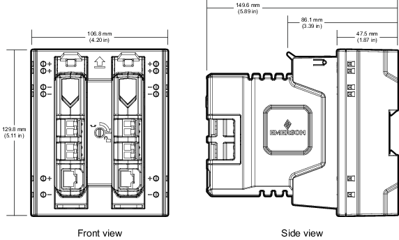
Dimensional Drawings

The following figures show the dimensions of the Media Converters and Media Converter Carrier.
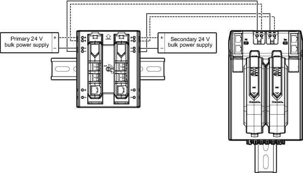
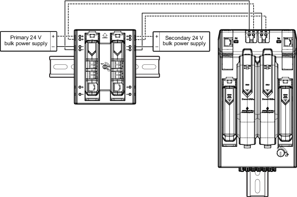
Figure: Dimensions of the Media Converters and Media Converter Carrier


Wiring Diagrams

The Media Converters are unmanaged devices and do not generate alarms to the DeltaV system. Emerson recommends daisy-chaining Media Converters with DeltaV managed nodes such as the CIOC and CSLS, which generate power-failure alarms when necessary. The following figures show how to connect power to Media Converters.

Figure: Daisy-chaining power to a redundant pair of Media Converters with a CIOC


Figure: Daisy-chaining power to a redundant pair of Media Converters with a CSLS