Installation notes
- The DI Plus Mass Connection Board provides an interface to the redundant DI 32-channel 24 VDC dry contact Plus card in redundant mode only.
- Two DI Plus Mass Connection Boards (the DI Plus Mass Connection Solution) are required to provide the interface to all 32 channels on the redundant DI 32-channel 24 VDC dry contact Plus card.
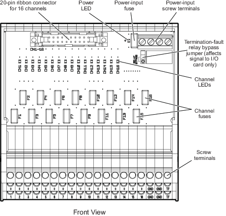
- Two 20-pin ribbon cables (one per board) connect between the DI Plus Mass Connection Solution and the Redundant Discrete Input 40-pin Mass Terminal Block.
- When the redundant DI 32-channel 24 VDC dry contact Plus card is used with the Redundant Discrete Input 40-pin Mass Terminal Block and the DI Plus Mass Connection Solution, the card can be configured to detect termination faults. Two parameters, T1_FAULT_DETECT (for the ribbon cable connection for channels 1-16), and T2_FAULT_DETECT (for the ribbon cable connection for channels 17-32), can be enabled in DeltaV Explorer for the card. Setting these parameters to True enables the system to detect faults such as loss of power, a missing cable, or a missing Mass Connection Board.
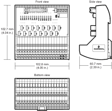
- Four screw terminals provide the connections for +24 VDC power and ground.
- The DI Plus Mass Connection Board provides a relay output to detect termination faults that indicate loss of input power to the board.
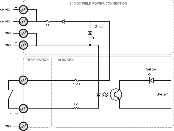
- For dry contact mode, connect your device between + and n, where n = 1-16. Refer to the dry contact wiring diagram below.
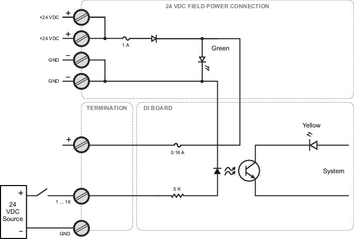
- For external power mode, connect the positive voltage output of your device to one numbered screw terminal n, where n = 1-16, connect the return of the device to the ground bar, and connect the ground bar to the GND terminals. Refer to the external power mode wiring diagram below.
- Power-input and channel fuses can be replaced in the field.
Note
The termination fault detection feature is available only when the redundant DI 32-channel 24 VDC dry contact Plus card is used with the Redundant Discrete Input 40-Pin Mass Terminal Block connected to the DI Plus Mass Connection Solution.