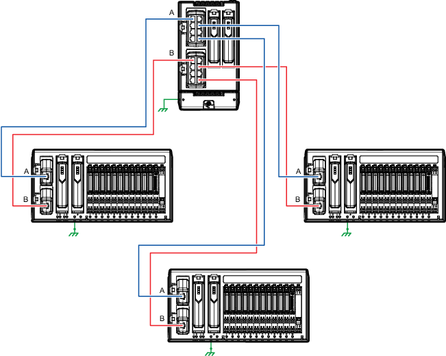
The following image shows CHARM I/O Blocks in a star topology.
Notes
- In a star topology, always connect A ports to A ports and B ports to B ports as shown in the figure.
- The Ethernet shield of each A port must be capacitively coupled through the Faraday shield of the RJ45 port to the DC (-) return.
- Use conductive shield termination at the CHARM I/O Gateway and non-conductive shield termination at each CHARM I/O Block.
- This is a 100 meter (maximum) straight-through or crossover cable.
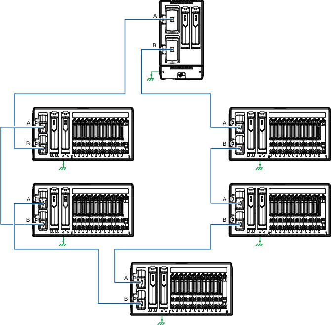
The following image shows CHARM I/O Blocks in a ring topology.
Notes
- In a ring topology, always connect A ports to B ports as shown in the figure.
- The Ethernet shield of each A port must be capacitively coupled through the Faraday shield of the RJ45 port to the DC (-) return.
- Use conductive shield termination at each B port and non-conductive shield termination at each A port.
- In a ring topology, the Ethernet shield of each B port must be tied directly to chassis ground.
- This is a 100 meter (maximum) straight-through or crossover cable.