Installation notes
- The following information applies only to part numbers 1X00797H01L and KJ1503X1-BB4. For other DeltaV bulk power supplies with similar characteristics, you can obtain documentation from Emerson Global Support Center at 800-833-8314.
- Install this bulk power supply on a horizontally oriented DIN rail with the label text right-side up.
- Keep the following installation clearances: 40 mm on top, 20 mm on the bottom, 5 mm on the left and right sides when the device is loaded permanently with more than 50% of the rated power. Increase this clearance to 15 mm if the adjacent device is a heat source such as another power supply.
Specifications
Terminals and wiring
Screw terminals with IP20 finger safe construction are used. The terminals are suitable for field and factory wiring. Use wire that complies with local codes and regulations.
| Wire type | Input screw terminals | Output screw terminals | DC-OK spring-clamp terminals |
|---|---|---|---|
|
Solid wire |
Maximum wire gauge: 6 mm2; 10 AWG |
Maximum wire gauge: 16 mm2; 6 AWG |
Maximum wire gauge: 1.5 mm2; 16 AWG |
|
Recommended tightening torque: 1 N · m; 9 lb. · in. |
Recommended tightening torque: 2.3 N · m; 20.5 lb. · in. |
||
|
Stranded wire |
Maximum wire gauge: 4 mm2; 12 AWG |
Maximum wire gauge: 10 mm2; 8 AWG |
Maximum wire gauge: 1.5 mm2; 16 AWG |
|
Recommended tightening torque: 1 N · m; 9 lb. · in. |
Recommended tightening torque: 2.3 N · m; 20.5 lb. · in. |
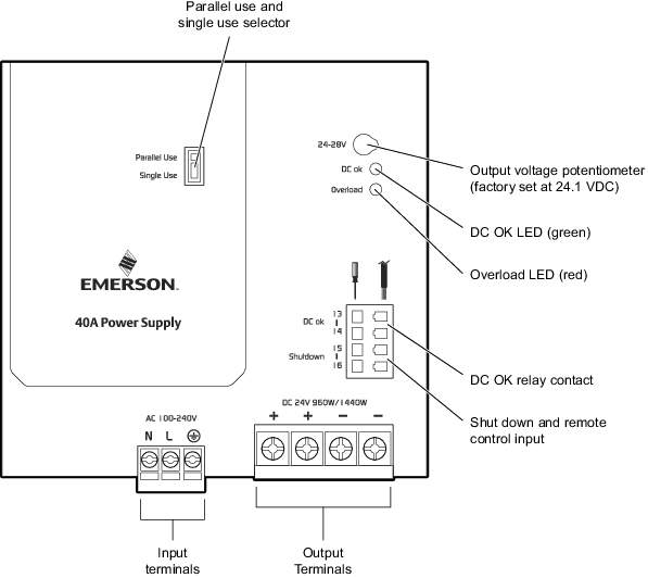
Connectors and LEDs
The following image shows the connectors and LEDs on the bulk power supply. The labels on the input and output terminals are self-explanatory (Neutral, Line, protective earth, positive (+) and negative (-) output). Additional information about the relay contact, shut down and remote control operations, and the parallel and single use selector follows the image. Refer to the Related information section for information on the LEDs.
DC OK Relay Contact operation
The DC OK relay contact monitors the bulk power supply's output voltage. It is synchronized with the DC OK LED.
- Closed contact: the output voltage has reached the adjusted output voltage level.
- Open contact: voltage has dipped to more than 10% below the adjusted output voltage. Short dips are extended to a signal length of 250 ms. Dips shorter than 1 ms are ignored.
- Reclosed contact: the output voltage has exceeded 90% of the adjusted voltage.
- Contact ratings maximum resistive load: 60 VDC at 0.3 A, 30 VDC at 1 A, 30 VAC at 0.5 A
- Contact ratings minimum permissible load: 1 mA at 5 VDC
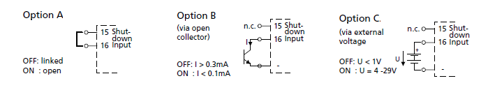
Shut down and remote control input operation
The shut down feature enables a signal switch or an external voltage to switch the power supply output off. The shutdown occurs immediately; the restart is delayed for up to 350 ms. In a shutdown condition, the output voltage is < 2 VDC and the output power is < 0.5 W. The voltage between different minus pole output terminals must be below 1 VDC when units are connected in parallel. The following image shows the various wiring options. When multiple power supplies are connected in series, only wiring option A with individual signal switches is allowed. Option C requires that the voltage source has current sink capability. Do not use a blocking diode.
Parallel and single use selector
Set the jumper to Parallel Use mode when power supplies are connected in parallel to increase the output power. In order to share the load current between the individual power supplies, parallel use regulates the output voltage such that the voltage at no load is approximately 4% higher than at nominal load. A missing jumper is the same as Single Use mode.