|
Fiber-optic cable is supplied by the end
user or the installer. The type of fiber-optic cable that can be used depends
on the type of optional fiber-optic transceivers that are selected at time of
sale. The transceivers that are available are single mode and multimode, and
they support various fiber diameters such as 62.5/125 micron, 50/125 micron in
multimode, and 9 micron in single mode. Use information in pre-sales literature
to determine cabling distances supported by the various types of fiber optic
transceivers.
|

|
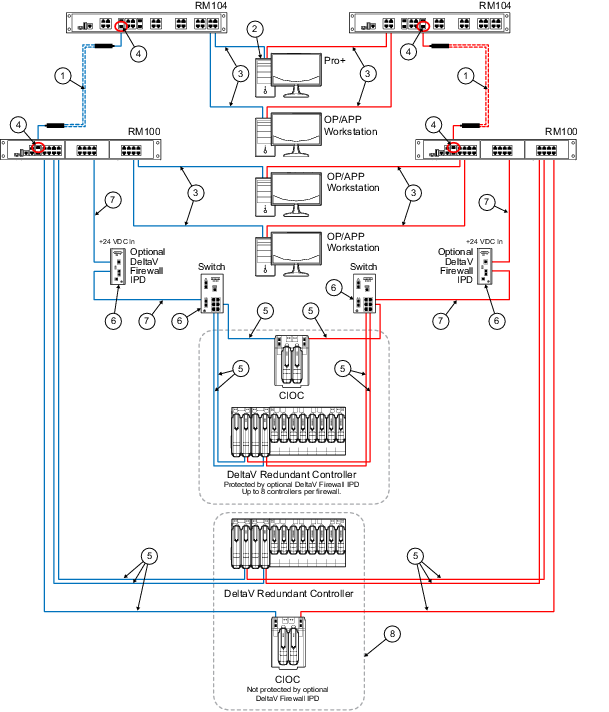
The ProfessionalPLUS is connected to any
RM104 port in this case so that there is a gigabit link between the
ProfessionalPLUS and the switch. Alternately, the ProfessionalPLUS could be
connected to any 100 mb/s port on the RM100 switches, or to one of the two
gigabit ports available on the RM100. Initially selecting a gigabit port for
the ProfessionalPLUS connection on any of the Smart Switches provides the most
available bandwidth.
|

|
This is a 100 meter (maximum)
straight-through or crossover cable. To prevent ground loops, build this cable
assembly with a shielded, metal-enclosed RJ45 connector on one end and an
isolated, plastic-enclosed RJ45 connector on the other end. The metal connector
end of this cable assembly must be placed on the switch and not on the PC.
Refer to
Building twisted pair cable assemblies
in the DeltaV Hardware Installation manual for more information.
|

|
The RM104 and RM100 Smart Switches contain
these combination ports. When there is a fiber-optic SFP slot next to a
twisted-pair slot as highlighted for this note, one or the other in that pair
can be used simultaneously, but not both. For the RM104, there are 4
combination ports, up to 4 ports in this grouping can be used, but never two
directly adjacent ports. For the RM100, there are 2 combination ports, up to 2
ports in this grouping can be used, but never two directly adjacent ports.
|

|
This is a 100 m (maximum) straight-through
or crossover cable. The shield on the CIOC and Controller's RJ45 connector
connects only to a Faraday cage in the CIOC or Controller; not to the CIOC or
Controller's DC ground. Therefore, the RJ45 connectors are floating and the
single point of ground is made at the switch to which the CIOC or Controller is
connected. Build this cable assembly with a shielded, metal-enclosed RJ45
connector on both ends. Refer to
Building twisted pair cable assemblies
in the DeltaV Hardware Installation manual for more information.
|

|
Ground screw must be attached to a
suitable ground for the shielding.
|

|
This is a 100 meter (maximum)
straight-through or crossover cable. To prevent ground loops, build this cable
assembly with a shielded, metal-enclosed RJ45 connector on the end that goes to
the Smart Switch, and the plastic-enclosed RJ45 connector on the end that goes
to the firewall IPD.
|

|
This example shows that when Controllers
and CIOCs are directly connected to the same switch as the workstations, they
are not protected by a firewall IPD. The firewall IPD is an option that allows
additional security; however, it is not required for normal DeltaV operation.
|