The DeltaV system supports the I.S. AO, 8-channel, 4-20 mA card and the I.S. AO, 8-channel, 4-20 mA, HART card.
Installation Notes
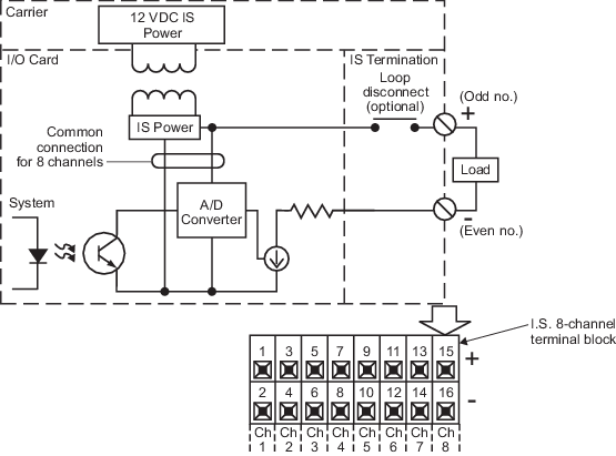
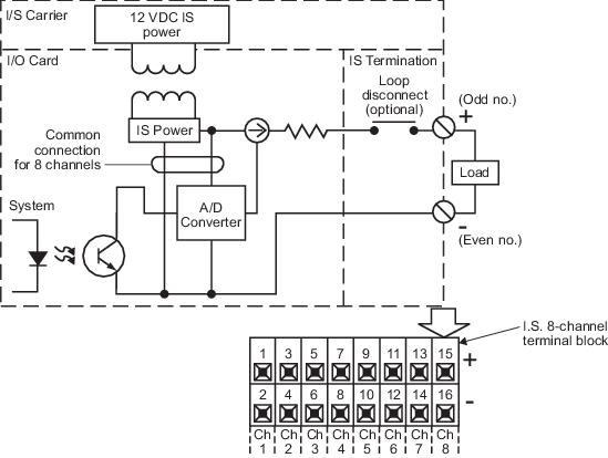
The I.S. 8-channel terminal block is recommended to provide screw terminations for field wiring for the HART and non-HART versions of the I.S. AO, 8-channel, 4-20 mA card. An optional block is the I.S. loop disconnect 8-channel terminal block.
Specifications
| Item | Specification |
|---|---|
| Number of channels | Eight |
| Isolation |
LocalBus to any channel: 60 VAC
Between channels: None I.S. channel to non-I.S. rail: 250 VAC |
| Nominal signal range (span) | 4 to 20 mA |
| Full scale signal range | 1 to 22 mA |
| Voltage to load | 13 V minimum @ 20 mA |
| Load resistance | 450 Ω maximum 650 Ω maximum with HART |
| LocalBus current (12 VDC nominal), per card | 630 mA |
| Open circuit detection threshold | 0.7 mA ±0.2 mA |
| Accuracy (@ 25 °C) | ±20 µA |
| Accuracy over temperature range | ±0.006% of span per °C |
| Accuracy over EMC conditions | 0.5% of span |
| Resolution | 12 bits |
| Output compliance | 20 mA stored into 450 Ω load; independent of supply (non-HART) 20 mA stored into 650 Ω load; independent of supply (HART) |
| Optional loop disconnect | Yes |
| Calibration | Stored on card |
| Mounting | Assigned slot of I/O carrier |
 WARNING!
Before substituting an I.S. AO, 4-20 mA card with an I.S. AO, 4-20 mA, HART card, you must perform a loop analysis or reassess the field parameters. Refer to the following documents for valid field parameters:
- 12P1892, DeltaVTM Scalable Process System Class I Div.2 with Class I, II, III, Div. 1 Field Circuit Installation Instructions
- 12P2524, DeltaVTM I.S. I/O Code of Practice for Installation and Maintenance in Zone 2 Hazardous Areas
- 12P1990, DeltaVTM Scalable Process System with Zone 0 Field Circuits, Installation Instructions