Installation notes
- The DO Mass Connection Board provides an interface to the DO 32-channel 24 VDC high-side or high-side Plus card used with the 40-Pin Mass Terminal Block in simplex mode or with the Redundant Discrete Output 40-Pin Mass Terminal Block. The DO Mass Connection Board also provides an interface to the DO 8-channel 24 VDC high-side card used with the 16-Pin Mass Terminal Block.
- Four DO Mass Connection Boards (the DO Mass Connection Solution) are required to provide the interface to all 32 channels on the DO 32-channel 24 VDC high-side card.
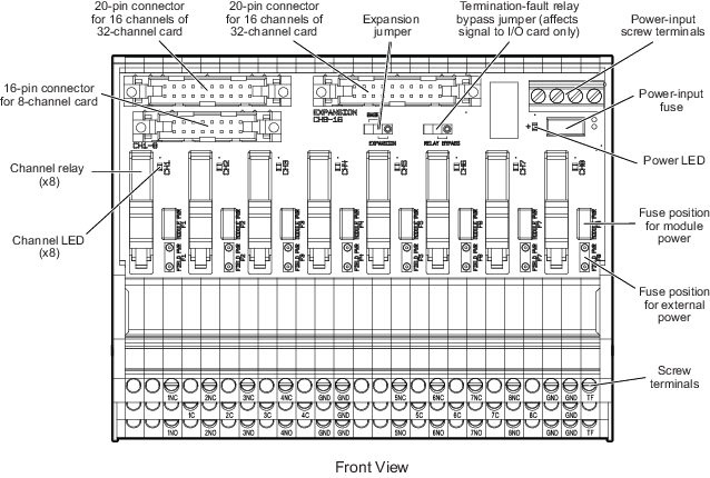
- Two 20-pin ribbon cables (one per board pair) connect the DO Mass Connection Solution to the 40-pin Mass Terminal Blocks. Two additional 20-pin ribbon cables connect each pair of DO Mass Connection Boards together, as shown in Figure: Connected DO Mass Connection Boards.
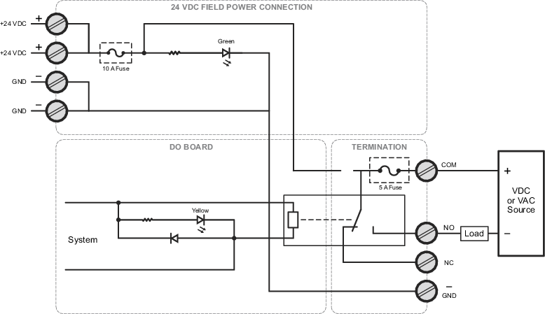
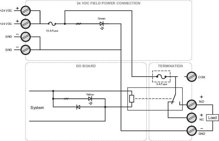
- The DO Mass Connection Board provides a relay output to detect termination faults that indicate loss of input power to the board.
- When the redundant DO 32-channel 24 VDC high-side Plus card is used with the Redundant Discrete Output 40-Pin Mass Terminal Block and the DO Mass Connection Solution, the card can be configured to detect faults in the termination. Two parameters, T1_FAULT_DETECT (for the ribbon cable connection for channels 1-16), and T2_FAULT_DETECT (for the ribbon cable connection for channels 17-32), can be enabled in DeltaV Explorer for the card. Setting these parameters to True enables detection of the ribbon cable connection between the Redundant Discrete Output 40-Pin Mass Terminal Block and the DO Mass Connection Board, and detection of faults such as loss of power, a missing cable, or a missing Mass Connection Board. You can disable termination-fault detection using a jumper on the board if you need to rewire while a process is running.
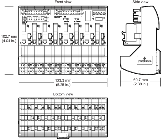
- Four screw terminals provide the connections for +24 VDC power and ground.
- If you are using an external +24 VDC source for a channel, move the fuse for that channel to the FIELD PWR position. Otherwise, leave the fuse in the MODULE PWR position. Refer to the parts locator and wiring diagrams for more information.
- The power-input fuse, channel fuses, and relays can be replaced in the field.
Note
Termination fault detection is available only when the redundant DO 32-channel 24 VDC high-side Plus card is used with the Redundant Discrete Output 40-Pin Mass Terminal Block connected to the DO Mass Connection Solution.