The DeltaV system supports the Sequence of Events card and the Series 2 Sequence of Events card in Simplex mode.
Installation Notes
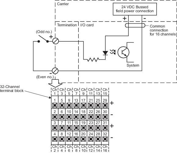
The 32-channel terminal block is recommended to provide screw terminations for field wiring for the Sequence of Events card and the Series 2 Sequence of Events card in Simplex mode. The 40-pin mass termination block also can be used. The following table lists the cable pin out connections for the Sequence of Events card
| Terminal | Channel Nomenclature | Terminal | Channel Nomenclature |
|---|---|---|---|
| Terminal 1 | Channel 1+ | Terminal 17 | Channel 9+ |
| Terminal 2 | Channel 1- | Terminal 18 | Channel 9- |
| Terminal 3 | Channel 2+ | Terminal 19 | Channel 10+ |
| Terminal 4 | Channel 2- | Terminal 20 | Channel 10- |
| Terminal 5 | Channel 3+ | Terminal 21 | Channel 11+ |
| Terminal 6 | Channel 3- | Terminal 22 | Channel 11- |
| Terminal 7 | Channel 4+ | Terminal 23 | Channel 12+ |
| Terminal 8 | Channel 4- | Terminal 24 | Channel 12- |
| Terminal 9 | Channel 5+ | Terminal 25 | Channel 13+ |
| Terminal 10 | Channel 5- | Terminal 26 | Channel 13- |
| Terminal 11 | Channel 6+ | Terminal 27 | Channel 14+ |
| Terminal 12 | Channel 6- | Terminal 28 | Channel 14- |
| Terminal 13 | Channel 7+ | Terminal 29 | Channel 15+ |
| Terminal 14 | Channel 7- | Terminal 30 | Channel 15- |
| Terminal 15 | Channel 8+ | Terminal 31 | Channel 16+ |
| Terminal 16 | Channel 8- | Terminal 32 | Channel 16- |
A Network Time Server is required for a Sequence of Events card.