Specifications
| Item | Specification |
|---|---|
| Voltage rating | 5 VDC |
| Maximum Current | 100 mA |
| Mounting | Assigned slot of I/O carrier. The lower slot number must be odd and the upper slot number must be the next higher even number. For example, slots 1 and 2, slots 3 and 4, and slots 5 and 6 are valid pairs. Slots 2 and 3 are not a valid pair. |
The Series 2 Plus Profibus DP cards in Redundant mode use the Redundant Profibus DP terminal block.
Do not plug a simplex Series 1 or Series 2 Profibus DP card into a Redundant Profibus DP terminal block. Only redundant Series 2 Plus Profibus DP cards can be used with the Redundant Profibus DP terminal block.
For simplex or redundant applications, when the termination is in the OUT position, pins 1 and 3 and 4 and 6 can be used. When the termination is in the IN position only pins 1 and 3 can be used.
The Redundant Profibus DP terminal block contains two latches for quick release. To remove the terminal block, depress both latches with a screw driver or finger and pull the terminal block down and off.
Terminal Block Connections
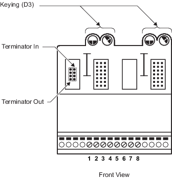
Gently tug on the jumper to remove it and then push the jumper onto a terminator position. The location of the terminal block on the segment determines the terminator position.
| Terminal Block Position | Terminator Position |
|---|---|
| End of segment |
IN A terminator in the IN position provides termination for the end of a segment. This type of termination is usually made with a single cable. |
| Middle of segment |
OUT A terminator in the OUT position provides a connection to other devices on the segment through the terminal block. These connections are typically made with two cables that run in two different directions (for example to two cabinets). The OUT position can also be used to connect two cables to a redundant DP/PA segment coupler for line redundancy. |
- When terminal blocks are located either at the middle of a segment or at the end of a long, single cable run, fiber-optic converters could be required in the line to provide isolation between the different locations. For example, a fiber-optic converter could be used to ensure that two cabinets installed in different buildings do not affect each other in terms of potential differences, surges, or hazardous area classification.
- When redundant DP/PA segment couplers are used for line redundancy or full duplex fiber-optic converters are used to isolate sections of the Profibus segment, be sure to properly configure status handling for the Profibus slaves in the control strategy. For example, be sure to configure the application software to determine the integrity and status of the slave device and the status of the communication to and from the slave device and the master.