-
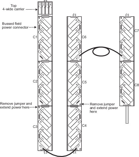
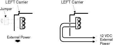
Remove the jumper on the 8-wide I/O interface carrier.
 WARNING!
Removing the jumper removes all 12 VDC power to all cards on all downstream carriers. When 12 VDC power is removed, cards are unable to hold the last value.
-
Insert 12 VDC power:
CAUTION!
On the right 8-wide Legacy Vertical carriers removing the jumper only disconnects the 96 pin carrier connector; it does not disconnect the 48 pin cable connector.
This caution only applies if power is extended to a right 8-wide Legacy Vertical carrier with a cable connected to it. As an example, in the configuration shown in the following figure power should be extended at carriers 3 and 5. This allows carriers 1 and 2 to receive power from the system power supply; carriers 3 and 4 to receive power extended at carrier 3; and carriers 5, 6, 7, and 8 to receive power extended at carrier 5.
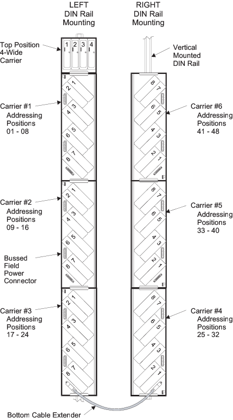
The following figure shows a typical Legacy Vertical configuration with six, 8-wide I/O interface carriers.
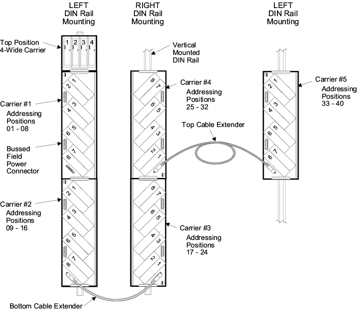
Another Legacy Vertical configuration uses the top cable extender to bridge a left to right 8-wide I/O Interface carrier, as shown here.
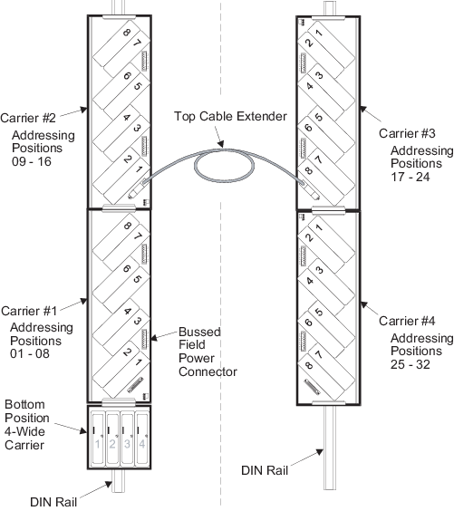
Another Legacy Vertical configuration, shown in the following figure, shows a bottom 4-wide Legacy Vertical carrier connected to a right 8-wide Legacy Vertical I/O interface carrier. A top cable extender bridges the right I/O carrier to a left I/O carrier on the back side of the cabinet.