|
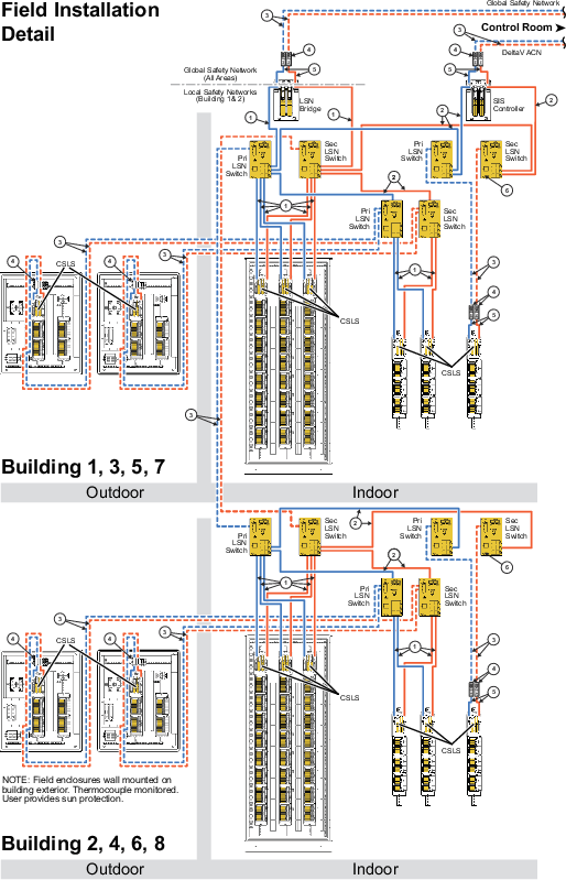
This is a 100 meter (maximum) straight-through or crossover
Category 5E Screened Twisted Pair (ScTP) cable. The shield on the RJ45
connector connects only to a Faraday cage in the Local Safety Network Bridge
(LSNB), the SZ controller, and the CSLS; not to these devices' DC ground.
Therefore, the RJ45 connectors are floating and the single point of ground is
made at the switch to which these devices are connected. Build this cable
assembly with a shielded, metal-enclosed RJ45 connector on both ends.
|

|
This is a 100 meter (maximum) straight-through or crossover
Category 5E Screened Twisted Pair (ScTP) cable. To prevent ground loops, build
this cable assembly with a shielded, metal-enclosed RJ45 connector on one end
and an isolated, plastic-enclosed RJ45 connector on the other end. The metal
connector end of this cable assembly can be placed on either end of the link.
|

|
Fiber-optic cable must be used for outdoor
building-to-building communications for immunity to electromagnetic
interference caused by near lightning strikes, for ground isolation between
buildings, and to gain additional distance that goes beyond the 100 meters (328
ft) maximum allowed for screened twisted pair cabling (ScTP).
|

|
This signal converter translates fiber-optic cable based
signals to copper based twisted pair Ethernet signals. Two are required; one
for the primary link and one for the secondary link.
|

|
This is a 100 meter (maximum) straight-through or crossover
Category 5E Screened Twisted Pair (ScTP) cable. The shield on the RJ45
connector connects only to a Faraday cage in the LSNB, the SZ Controller, and
the CSLS; not to these devices' DC ground. Therefore, the RJ45 connectors are
floating and the single point of ground is made at the attached signal
converter to which these devices are connected. Build this cable assembly with
a shielded, metal-enclosed RJ45 connector on both ends.
|

|
All DC powered switches in this figure contain a ground
screw. Be sure to attach a ground wire to this screw terminal to ground the
shields of the attached cables. See the switch's installation sheet for
details.
|