|
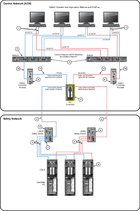
100 meter (maximum) straight-through or crossover cable. To
prevent ground loops, build this cable assembly with a shielded, metal-enclosed
RJ45 connector on one end and an isolated, plastic-enclosed RJ45 connector on
the other end. The metal connector end of this cable assembly must be placed on
the switch and not on the PC.
|

|
100 m (maximum) straight-through or crossover cable. The
shield on the SZ controller's RJ45 connector connects only to a Faraday cage in
the controller; not to the controller's DC ground. Therefore, the RJ45
connectors are floating and the single point of ground is made at the switch to
which the controller is connected. Build this cable assembly with a shielded,
metal-enclosed RJ45 connector on both ends.
|

|
100 m (maximum) straight-through or crossover cable. The
shield on the CSLS RJ45 connector connects only to a Faraday cage in the CSLS;
not to the CSLS DC ground. Therefore, the RJ45 connectors are floating and the
single point of ground is made at the switch to which the CSLS is connected.
Build this cable assembly with a shielded, metal-enclosed RJ45 connector on
both ends.
|

|
The SZ Controller completely isolates communications
between the DeltaV Control Network and the Safety Network. External cabling
should never be used to connect these two independent systems together.
|

|
The RM100 Smart Switches are managed through the DeltaV
console using the Network Device Command Center.
|

|
The LSN20 safety switches cannot be managed through the
Network Device Command Center. For network diagnostics for these switches, you
must attach an optional serial cable to the serial port of the safety switch
and use an application such as Hyper-terminal to access the switch information.
No configuration of the safety switch is possible though the serial port. The
switches are plug and play.
|

|
Attach the ground screw of the switch to a suitable ground
for the cable shields.
|

|
Attach the ground screw of the firewall to a suitable
ground for the cable shields.
|

|
Up to 16 CHARMs Smart Logic Solvers (CSLS) can be connected
within the Safety System architecture. In this example, the LSN20 switches,
which have a low port count, are used but an SRM100 rack mounted safety switch
with optional twisted pair port modules could be used so that the maximum of 16
CSLS can be attached.
|

|
100 meter (maximum) straight-through or crossover cable. To
prevent ground loops, build this cable assembly with a shielded, metal-enclosed
RJ45 connector on one end and an isolated, plastic-enclosed RJ45 connector on
the other end. The metal connector end of this cable assembly must be placed on
the switch and not on the PC.
|