CT_fp (Control Techniques VFD module faceplate)
Configuration view of the Control Techniques VFD (variable frequency drive) module faceplate (CT_fp)
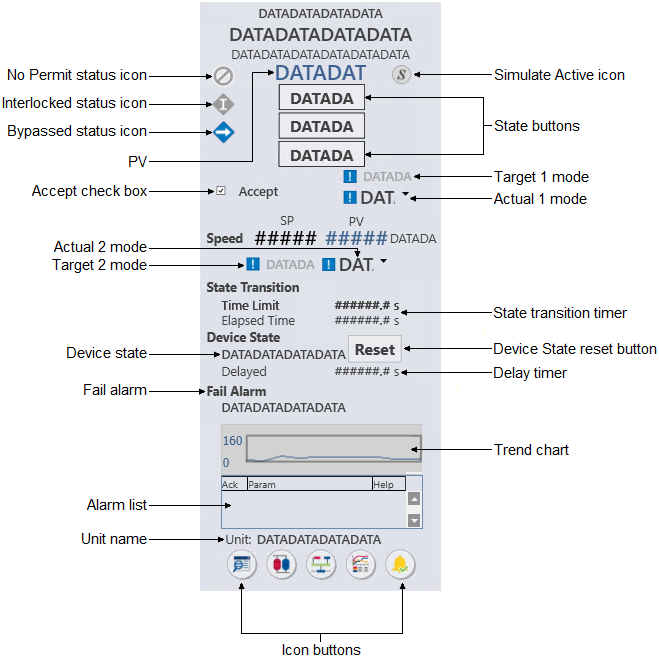
The CT_fp is used with the
CT-UNIM_F300 module template. The following list describes the major components
that are present on the CT_fp.
- PV
- Shows the module's PV value and the PV engineering units. The text color is based on the PV status (blue when the PV status is good and a shade of red when the status is uncertain or bad).
- No Permit status icon
-
Icon Status Description 
No Permit (Permissive condition) Visible when any of the following is true: For a DC block:-
DEVICE_OPTS parameter is set to Permissive
-
DC_STATE is set to Confirmed Passive
-
There is no permit
For an EDC block:-
Only the Device Option for Permissive is true, EDC block is in the passive state, and there is no permit
-
The Device Option for Permissive to Any State is true, and there is no permit
-
- Simulate Active status icon
-
Icon Status Description 
Simulate Active Visible per the Simulation Active condition in the module's BLOCK_ERR parameter. The Simulation Active icon is never visible if either the Not Running or Bad IO icon is visible. - Interlocked status icon
-
Icon Status Description 
Interlocked (Interlock condition) Visible when either of the following is true:-
The DC block's DC_STATE parameter is Shutdown/Interlock
-
The EDC block's OPERATION_STATE parameter is Shutdown/Interlock
-
- Bypassed status icon
-
Icon Status Description 
Bypassed Visible when the module level BYPASSED parameter is True. Interlock bypassed applies only to DC or EDC blocks. Tracking condition bypassed applies to all other function blocks - State buttons
- Depending on the type of discrete device being controlled, a faceplate provides either two or three state buttons, each labeled with a text description of its corresponding state. Click one of these buttons to set the target state (SP_D of the Device Control block) to the state described on the button (when the state is permitted).
- Accept check box
- Use this check box to toggle the ACCEPT_D parameter in the Device Control block. When Accept is checked, the actual state (PV_D) is set to the output state (OUT_D), regardless of the discrete input states that determine FV_D.
- Speed
- Displays the PV and SP current values for the speed of the motor.
- Target Mode
- Shows the target mode for the module. When the normal and target modes are not the same, an exclamation point displays to the left of the text.
- Actual Mode
- Shows the actual mode for the module. When the actual and target modes are not the same, an exclamation point displays to the left of the text.
- State transition timer
-
- Time Limit
- Shows the confirm time for the current setpoint of the Device Control block (for example, CFM_PASS_TIME when SP_D is passive).
- Elapsed Time
- Shows the transition timer that begins to increment when the outputs are driven as a result of a change in SP_D.
- Device state
- Shows the current state of the DC_STATE parameter in the Device Control block. When the device state is Locked, a reset button appears on the faceplate. Use the reset button to reset the device state.
- Device state reset button
- Resets the device state. This button is visible only when the device state is Locked.
- Delay timer
- Shows the module's DELAY_TIMER value - the time remaining for the delay or restart to be complete. The timer counts down to zero.
- Fail alarm
- Shows the current state of the FAIL parameter in the Device Control block. When the device state is Locked, a reset button appears on the faceplate. Use the reset button to reset the fail alarm state.
- Trend chart
- Provides a condensed version of a trend chart.
- Alarm list (active)
-
Provides a condensed version of an alarm summary and scrollable list of the module's current active alarms.
- Ack column --> Shows the state of the alarm, which is
represented by one of the following symbols:
Alarm state Ack column Active/unacked Empty field Active/acked Check mark Inactive/unacked Empty box - Param column --> Shows the alarm name or parameter. The text and colors are as configured for the alarm's current state.
- Help column --> Indicates the type of Alarm Help available
for the corresponding alarm. The column contains one of the following icons:
Icon Description 
Alarm Help is enabled. 
Alarm Help is not enabled but the user has the privilege to edit Alarm Help. No icon Alarm Help is not enabled and the user does not have the privilege to edit Alarm Help, or the system does not have a license for alarm help.
- Ack column --> Shows the state of the alarm, which is
represented by one of the following symbols:
- Unit name
- Shows the unit name.
- Icon buttons


