FFPid_dt (Fieldbus PID function block detail display)
Configuration view of the Fieldbus PID detail display (FFPid_dt)
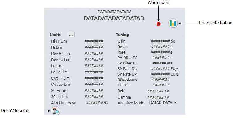
The FFPid_dt is used with the PID function block used with a Fieldbus PID Loop module. The following sections describe the major components that are present on the FFPid_dt.
- Alarm icon
- Shows the highest priority alarm for that module. The following
table shows the alarm icon for each alarm priority and state.
Active acknowledged Active unacknowledged Inactive unacknowledged Suppressed Critical alarm 


Warning alarm 


Advisory alarm 


- Faceplate button
- Opens the module faceplate display.
- Limits
-
- Hi Hi Lim
- The maximum value of the PV (in engineering units) before the High High Limit active bit (HI_HI_ACT) is set. Click this field to enter a new limit.
- Hi Lim
- The maximum value of the PV (in engineering units) before the High Limit active bit (HI_ACT) is set. Click this field to enter a new limit.
- Dev Hi Lim
- The maximum positive deviation of the PV from SP (in engineering units) before the High Deviation Limit active bit (DV_HI_ACT) is set. Click this field to enter a new limit.
- Dev Lo Lim
- The maximum negative deviation of the PV from SP (in engineering units) before the Low Deviation Limit active bit (DV_LO_ACT) is set. Click this field to enter a new limit.
- Lo Lim
- The minimum value of the PV (in engineering units) before the Low Limit active bit (LO_ACT) is set. Click this field to enter a new limit.
- Lo Lo Lim
- The minimum value of the PV (in engineering units) before the Low Limit active bit (LO_ACT) is set. Click this field to enter a new limit.
- Out Hi Lim
- The maximum value, in engineering units, of the output. Click this field to enter a new limit. (The valid input range for this value is -10 to 110 % of the output scale, in engineering units.)
- Out Lo Lim
- The minimum value, in engineering units, of the output. Click this field to enter a new limit. (The valid input range for this value is -10 to 110 % of the output scale, in engineering units.)
- SP Hi Lim
- The maximum value of the SP, in engineering units. Click this field to enter a new limit. (The valid input range for this value is -10 to 110 % of the PV Scale, in engineering units.)
- SP Lo Lim
- The minimum value of the SP, in engineering units. Click this field to enter a new limit. (The valid input range for this value is -10 to 110 % of the PV Scale, in engineering units.)
- Alm Hysteresis
- The alarm hysteresis (or deadband) value for the alarm conditions in % of OUT scale. Click this field to enter a new value. An alarm condition does not recur until the PV has backed away from the corresponding limit by at least the % of OUT Scale specified by this value.
- Tuning
-
- Gain
- The gain used in the PID algorithm.
- Reset
- The integral time constant used in the PID algorithm.
- Rate
- The derivative time constant used in the PID algorithm.
- PV Filter TC
- The PV filter time constant in seconds.
- SP Filter TC
- The PV filter time constant in seconds.
- SP Rate DN
- In engineering units, the maximum negative change to the WORKING_SP that are allowed per second (SP_RATE_DN). Click this field to enter a new value. A value of 0.0 indicates that no rate limiting will be done.
- SP Rate UP
- In engineering units, the maximum positive change to the WORKING_SP that are allowed per second (SP_RATE_UP). Click this field to enter a new value. A value of 0.0 indicates that no rate limiting will be done.
- IDeadband
- The integral deadband. When the error (WORKING_SP minus PV) is less than this value, integral action stops.
- FF Gain
- The feedforward gain (FF_GAIN). This field is visible when FF_ENABLE is True.
- Beta
- The fraction of proportional action taken on error versus PV. The valid input range is 0.00 to 1.00. This field is visible when STRUCTURE is set to Two Degrees of Freedom Controller.
- Gamma
- The fraction of derivative action taken on error versus PV. The valid input range is 0.00 to 1.00. This field is visible when STRUCTURE is set to Two Degrees of Freedom Controller.
- Adaptive Mode
- The Actual and Target modes. Click the drop–down arrow to change the Target mode.
- DeltaV Insight button
- Launches DeltaV InSight in the context of this module.