Loop_Ramp_fp (Loop Ramp module faceplate)
Configuration view of the Loop Ramp module faceplate (Loop_Ramp_fp)
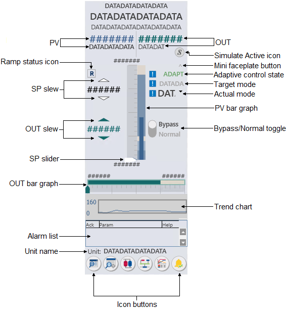
- PV
- Shows the module's PV value and the PV engineering units. The text color is based on the PV status (blue when the PV status is good and a shade of red when the status is uncertain or bad).
- OUT
- Shows the module's OUT value and engineering units. The text color is based on the OUT status (green when the PV status is good and a shade of red when the status is uncertain or bad).
- Simulate Active status icon
-
Icon Status Description 
Simulate Active Visible per the Simulation Active condition in the module's BLOCK_ERR parameter. The Simulation Active icon is never visible if either the Not Running or Bad IO icon is visible. - Ramp status icon
- Indicates the current state of the ramp, as indicated in the
following table:
Icon Ramp state 
Ramping - The ERAMP_ACTIVE parameter value is 1 (True) and the ERAMP_STATE parameter is set to Ramping. 
Paused - The PAUSE parameter is set to 1 (True) when the ramp is active or the ERAMP_STATE parameter is set to Paused when the Pause if mode changes option is enabled and the current target block mode does not match the ERAMP_IN_MODE parameter. None The ramp is not in the Ramping or Paused state. - SP slew
- Provides a means to manually modify the setpoint value. Click the slew arrows to increase or decrease the setpoint. The increments by which the setpoint changes with each mouse click are based on a percent of the PV range. The default percent is 1%. Alternatively, you can enter a value in the SP value field.
- Mini faceplate button
- Opens a smaller version of a main faceplate. The mini faceplate shows only the module's critical values.
- Adaptive control state
- Indicates that an Adapt license has been assigned to the block, and the Actual Adapt mode or Target Adapt mode is not Off. When the actual and target modes are not equal, an exclamation point displays to the left of the text.
- Target Mode
- Shows the target mode for the module. When the normal and target modes are not the same, an exclamation point displays to the left of the text.
- Actual Mode
- Shows the actual mode for the module. When the actual and target modes are not the same, an exclamation point displays to the left of the text.
- PV bar graph
-
Presents PID, AI, or ALM information graphically, relative to the defined EU0 and EU100.
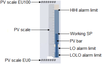
- PV bar
- Graphically indicates the PV value.
- PV scale EU0 and EU100
- Shows the values that correspond to 0% and 100% of scale, respectively, for the PV.
- PV scale lines
- Shows the major and minor divisions for the scale.
- PV alarm limits
- Indicates the HI HI, HI, LO, and LO LO alarm limits for the PV. Alarm limits can be modified using the module's detail display.
- OUT slew
- Provides a means to manually modify the output value. Click the slew arrows to increase or decrease the output by increments of 1 engineering unit, or enter a value in the OUT value field.
- Bypass/Normal toggle
- This control provides a means to place the PID block in Bypass mode and return it to Normal mode. Bypass mode makes the output value equal to the percent of SP value, which allows the master loop to drive the output if the transmitter is unavailable. Click Bypass to place the PID block in Bypass mode, or click Normal to turn off the Bypass mode.
- SP slider
- Use the setpoint slider to modify the setpoint value by dragging
the slider to the desired point on the scale. The new value is then written to
the module's SP parameter.
Another arrowhead (not shown in this image), with the same size and movement range as the Setpoint slider, indicates the Working Setpoint (SP_WRK) of the loop. This arrow's movement range is restricted within the setpoint limits and is the actual SP used by the controller to calculate output moves. When SP and SP_WRK have the same value, SP_WRK is superimposed upon SP and, therefore, is not distinguishable from SP. The Working Setpoint is visible as a separate entity when setpoint ramping prevents SP_WRK from going to SP immediately.
- OUT bar graph
-
- OUT bar
- Indicates the value of the OUT parameter, which is the same as the value shown in the OUT value field.
- OUT scale EU0 and EU100
- Shows the values that correspond to 0% and 100% of the OUT_SCALE parameter.
- OUT scale lines
- Shows the major and minor divisions for the scale.
- OUT LO and HI limits
- Shows the warning limits for OUT.
- Trend chart
- Provides a condensed version of a trend chart.
- Alarm list (active)
-
Provides a condensed version of an alarm summary and scrollable list of the module's current active alarms.
- Ack column --> Shows the state of the alarm, which is
represented by one of the following symbols:
Alarm state Ack column Active/unacked Empty field Active/acked Check mark Inactive/unacked Empty box - Param column --> Shows the alarm name or parameter. The text and colors are as configured for the alarm's current state.
- Help column --> Indicates the type of Alarm Help available
for the corresponding alarm. The column contains one of the following icons:
Icon Description 
Alarm Help is enabled. 
Alarm Help is not enabled but the user has the privilege to edit Alarm Help. No icon Alarm Help is not enabled and the user does not have the privilege to edit Alarm Help, or the system does not have a license for alarm help.
- Ack column --> Shows the state of the alarm, which is
represented by one of the following symbols:
- Unit name
- Shows the unit name.
- Icon buttons


