Because the Logic Solver is a De-energized to Trip environment the normal operating value of the output is On (1) and the tripped value is Off (0).
To use the LSDO block in a safety shutdown application, assign IO_OUT to a Logic Solver Discrete Output channel or LS CHARM connected to a valve controller. Typically, the CAS_IN_D input of the LSDO block would be wired from an EFFECT output of an upstream LSCEM block. Default LSDO block behavior passes the value of CAS_IN_D to OUT_D.
You can wire feedback from the final element to the RDBK_IN_D input parameter of the LSDO block. This input would typically be wired from an LSDI function block representing a limit switch. The RDBK_IN_D value becomes the PV_D of the LSDO block. If the configurable time CFM_TRIP_TIME expires before PV_D confirms the off state, the DO_ALERTS Failed to confirm after trip command becomes True. If RDBK_IN_D is not wired, PV_D has the same value as OUT_D, so confirmation is immediate.
Fault State Detection
The LSDO block enters a fault state when any of three conditions is detected and a corresponding option has been selected for the detected condition. When the fault state is active, the block forces OUT_D to Off, sets the Fault State Active bit in BLOCK_ERR, and sets FAULT_STATE to Active. The FSTATE_OPTS options are selected by default and include:
-
Enable detection based on CAS_IN_D status
If the status of CAS_IN_D becomes Bad, FSTATE_TIMER begins incrementing from 0.0. If the status remains Bad for FSTATE_TIME seconds, OUT_D is forced to Off (0). FSTATE_TIMER continues to increment while the status of CAS_IN_D is Bad. The fault state condition clears immediately when the status transitions away from Bad.
-
Enable detection based on output status
OUT_D is forced to Off if the Logic Solver detects a short or open in the field wiring (status of OUT_D is Bad SensorFailure LowLimited) while OUT_D is being commanded On. The LSDO block reacts to this status by forcing the output Off to track the state of the final element. Note that FSTATE_TIME has no effect when the fault state is a result of OUT_D status.
NoteIf you use this option you must also require a reset, either in this block or in an upstream LSCEM block, because an active fault state condition clears when the block drives the output Off. Requiring a reset prevents the block from driving the output back to On during the next scan.
-
Enable detection based on PV_D value
OUT_D is forced to 0 based on feedback from the final element wired into RDBK_IN_D. The final element is confirmed Off (PV_D is 0) while OUT_D is commanded On. Use this option to force the output Off if a failure of the final element is not detected by a Logic Solver diagnostic. RDBK_IN_D should be wired when using this option, otherwise PV_D has the same value as OUT_D. Note that FSTATE_TIME has no effect when the fault state is a result of the value of PV_D.
NoteIf you use this option you must also require a reset, either in this block or in an upstream LSCEM block, because an active fault state condition clears when the block drives the output Off. Requiring a reset prevents the block from driving the output back to On during the next scan.
FSTATE_TIMER is a writeable parameter. Be advised that writing to FSTATE_TIMER can cause the state of OUT_D to change depending on the value written.
Determining the Value of OUT_D and Writing the Output Value
The following figure is the state transition diagram for OUT_D_STATE. When OUT_D_STATE is Off or Off - Ready to Reset, the value of OUT_D is Off (0) and the Logic Solver channel or LS CHARM defined by IO_OUT is written to Off. When OUT_D_STATE is On, OUT_D is On (1) and IO_OUT is written to On.
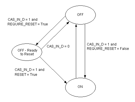
To require a manual reset to transition OUT_D to On (1), it is recommended that you configure this in an upstream LSCEM block, not the LSDO block. The LSCEM block has a number of features that enhance the reset logic. The ability to require resets in the LSDO block (using the REQUIRE_RESET parameter) is provided if you do not have voter and LSCEM blocks to implement shutdown logic.
If you set the LSDO block's REQUIRE_RESET parameter to True, any transition of OUT_D to Off (0) causes OUT_D to remain Off until all of the following conditions are met:
RESET should be changed to True using a button on a faceplate or process display in the operator environment. The block changes RESET back to False. Do not expose RESET as an input on the block and wire to it. If you need to reset an LSDO block from SIS module logic, use an LSCALC function block to do a conditional assignment to RESET.
When OUT_D_STATE is Off or Off - Ready to Reset, the value of OUT_D is 0 and the channel or LS CHARM on this Logic Solver defined by IO_OUT is written to Off.
When OUT_D_STATE is On, OUT_D is 1 and the channel or LS CHARM is written to On.
Determining the Value of PV_D
PV_D normally gets its value from RDBK_IN_D. If the status of RDBK_IN_D is BadNotConnected, PV_D has the same value as OUT_D. Use the invert input option in the upstream LSDI function block if you are using a closed limit switch. You can manipulate PV_D to test an operator display or test the confirmation alarm condition by using simulation in the upstream input function block (simulation available when the Logic Solver is assigned to the ProfessionalPLUS workstation as a simulated Logic Solver card).
Determining the Value of DO_ALERTS
The DO_ALERTS parameter reports two alarm conditions set by the block (inactive = 0, active = 1):
-
Failed to confirm after trip command
The device fails to confirm after being commanded to trip. On any transition of OUT_D to Off, the block starts a confirmation timer. If the value of PV_D is not 0 within CFM_TRIP_TIME seconds, the alert Failed to confirm after trip command becomes True. The alert clears when OUT_D transitions to On (1) or PV_D transitions to Off (0).
-
Confirm lost while commanded On
The device confirms Off while it is being commanded On. When OUT_D_STATE is On and PV_D has transitioned to 1, the condition is detected if PV_D becomes 0, for example if the device has a failure that causes it to confirm in the Off state. The alert clears on the next transition of OUT_D_STATE to On.
Event Generation
The LSDO block generates an event record when any of the following conditions become active and the REPORT_OPTS option Event records are not generated is not selected:
-
The block has set DO_ALERTS Failed to confirm following a command to trip. The event record shows the path to the LSDO block and the Failed to confirm after trip command text string along with the time of occurrence.
-
The block has set DO_ALERTS Confirm lost while commanded On. The event record shows the path to the LSDO block and the text Confirm lost while commanded On along with the time of occurrence.
-
The command to trip was successful and RDBK_IN_D has been wired. The event record shows the path to the LSDO block and the text Successful confirmation following a command to trip along with the time of occurrence.