The following block diagram shows a simple application that uses the LSDO block to operate a solenoid valve.
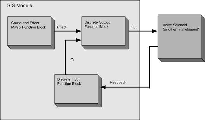
In this example, the input to the Logic Solver Discrete Output block is an effect output from a Cause and Effect Matrix block. During normal operation the effect output's value is 1 (one). When the inputs to the Cause and Effect Matrix block indicate a hazardous condition exists, the effect output is set to 0 (zero). This, in turn, trips the output of the Discrete Output block, driving the associated Logic Solver channel or LS CHARM to close the valve.
The Logic Solver Discrete Input block is wired to a limit switch or other indicator to confirm that the valve closes. If the valve does not close, the PV input to the Discrete Output block from the Discrete Input block eventually sets a fault state in the Discrete Output block.
This simple example does not illustrate a number of configurable functions the block supports: