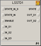
The LSSTD function block implements a user-defined state machine in the Logic Solver. A state machine describes the possible states, and the transitions between those states, that can occur in a system. The combination of LSSTD and LSSEQ blocks provide a sequencing capability similar to DeltaV Sequential Function Charts (SFC). LSSTD blocks associate transitions with system states. LSSEQ blocks associate system states with actions.
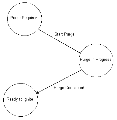
State machines may be described by state transition diagrams. For example, a burner management system could be defined by the following diagram of the allowed transitions (arrows) between system states (circles).
The block's MATRIX parameter describes the state diagram (the association of states and input transitions).
The LSSTD block does not support modes or alarm detection.
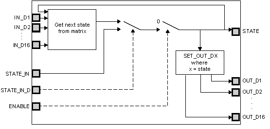
The following diagram shows the internal components of the LSSTD function block.