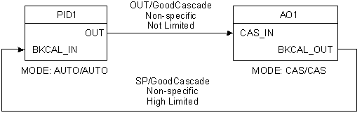
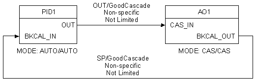
The BKCAL parameters are used for interblock communication, specifically to let upstream blocks know the status of downstream blocks. Blocks that utilize the BKCAL parameters are referred to as cascaded blocks. When cascaded, the blocks act as a control unit that must coordinate its control activity.
The BKCAL parameters include a BKCAL_OUT parameter in a downstream block connected to a BKCAL_IN parameter in an upstream block. The downstream block passes a value (usually its setpoint) as well as a status to the upstream block. When the upstream block executes its algorithm, it takes into account the status of the downstream block. The most common use of BKCAL is to prevent reset windup. In other words, if a downstream block is in a limited state, it sends the limited status to the upstream control block, which turns off its integral action in response, as shown in the following figure.
Cascade initialization
Another use of the BKCAL parameters is to initialize cascaded blocks. This occurs when the control cascade is automated (for example, when the blocks go from Manual to Auto or Cas mode). The simplest case of a control cascade is a master PID block linked to a slave AO block. The dialog that takes place between blocks during this process is shown in the following sequence of figures.
Step 5 shows the fully automated cascade. The target mode of the master controller is set to Auto. Since PID1/BKCAL_IN has a status other than Not Invited (because the slave block is in Cas mode), the PID block is authorized to go to Auto mode. Note that if the user had set the target mode of PID1 to Auto at step 1, the block would have remained with mode Auto/IMan because of the Not Invited status received by the PID through BKCAL_IN.
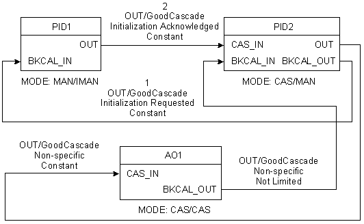
Multi-level cascade initialization
The following figure shows the initialization process for a multi-level cascade (that is, a cascade with two levels of cascading). This figure illustrates a control cascade with a downstream AO block. Cascade automation starts from the most downstream block and proceeds step by step upstream. When these steps are completed, all blocks in the cascade are in Cas mode except the master block, which is in Auto mode when the cascade is fully automated.
The preceding examples regarding Cas mode also apply to RCas mode. The same communication takes place between the master and slave blocks. However, in RCas mode, substitute RCAS_IN for CAS_IN and RCAS_OUT for BKCAL_OUT.