You select how the outputs are calculated with parameter configuration. The inputs wired to the block determine the outputs.
Calculating Outputs
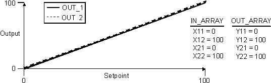
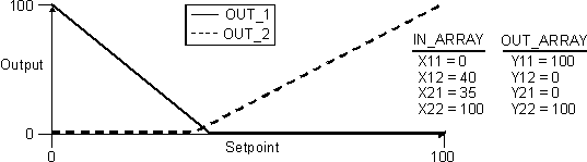
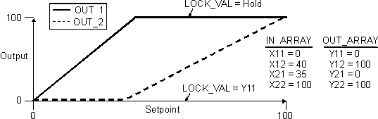
The block outputs (OUT_1 and OUT_2) are calculated from the block setpoint (SP) using the slope and limits established by the IN_ARRAY and OUT_ARRAY parameters. The four values of the IN_ARRAY determine the SP range used to calculate outputs based on the four values of the OUT_ARRAY output range. The following table illustrates the relationship between the block outputs and the array elements:
|
Block Output |
IN_ARRAY Element |
OUT_ARRAY Element |
||
|---|---|---|---|---|
|
Starting SP Value |
Ending SP Value |
Output Value for Starting SP Value |
Output Value for Ending SP Value |
|
|
OUT_1 |
X11 |
X12 |
Y11 |
Y12 |
|
OUT_2 |
X21 |
X22 |
Y21 |
Y22 |
Some constraints are enforced by the controller to guarantee useful output values:
Violation of any of these constraints locks the block into OOS mode and sets the BLOCK_ERR parameter to Configuration Error.
The OUT_1 parameter is set to Y11 when the SP value exceeds X12 when the LOCKVAL parameter is defined as follows:
OUT_1 is Y11 when SP > X12
A configured hysteresis (default value equal to five percent of the X11-to-X12 span) is used to prevent OUT_1 from jumping between Y11 and Y12 at X12.
The following figures show the output values for three examples of IN_ARRAY and OUT_ARRAY elements:
Setpoint Limiting
The setpoint is limited to the endpoints of the IN_ARRAY parameter values.
In Auto mode, you can apply rate of change limits to the setpoint by configuring the SP_RATE_UP and SP_RATE_DN parameters. Rate limiting applies only in Auto mode.
Block Errors
Block configuration error — The block is wired to a HART channel and the HART device indicates that the function block's units are not compatible with the device. In this case, the Out of Service block error is also set.
Simulate active — Simulation is enabled and the block is using a simulated value in its execution.
Input failure/process variable has Bad status — The source of the block's process variable is bad. Indicates a hardware failure, a non-existent Device Signal Tag (DST), or a Bad status on the SIMULATE parameter.
Local Override — The block is in Local Override (LO) mode.
Out of Service — The block is in Out of Service (OOS) mode.
Output failure — The status of BKCAL_IN_1 or BKCAL_IN 2 is Bad.
Other Error — The status of CAS_IN is Bad.