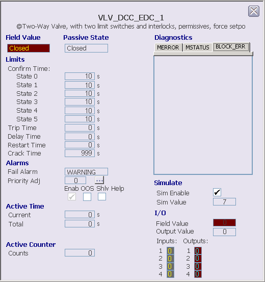
The following items are contained in the EDC module detail display:
- Field Value - This text field contains the state name (FV_D) that corresponds to the discrete input pattern being read from the field.
- Passive State - The state selected as the passive state.
- Limits - This area
contains the following fields:
- Confirm times Stat 0 through 5 - The values of CFM_STATEn_TIME.
- Trip Time - This field displays the maximum time period for which a loss of confirmation from the device can exist before the device is considered to have tripped and a transition to the passive state is initiated. This value is only applicable when the trip option is enabled in DEVICE_OPTS in the Device Control block. If this time is exceeded, a fail alarm is generated. Click this field to enter the time.
- Delay Time - This field displays the time that a change in SP_D to an active state is delayed before the corresponding discrete output pattern is written to the outputs. Click this field to enter the time.
- Restart Time - This field displays the time that OUT_D is held in the passive state when transitioning from one active state to another before it is driven to the new active state. A restart time other than 0 is typically used on a forward-reversing motor or on a two-state motor to prevent it from restarting until it has been stopped for the restart time. Click this field to enter the time.
- Crack Time - This field displays the time allowed for a change in confirmation of the state being left. If this time is exceeded, a fail alarm is generated. Crack time can be used to detect whether a valve with a long travel time has begun to move to a new position so that faster alarm detection is possible. Typically, crack time is set shorter than the confirm times for a valve but longer than the confirm times for a motor. Click this field to enter the time.
- Alarms - This area contains the following items:
- Active Time - Contains fields that show the time in the current active state and the total time in active states.
- Active Counter - Shows the number of times the EDC block has been in an active state.
- Diagnostics - This section displays visible text for active conditions in the module's MERROR, MSTATUS, and BLOCK_ERR parameters. There is a tab for each parameter. The parameter name on the tab is underlined when an active condition for that parameter is displayed. When an error has occurred in the module, a Clear Error button is displayed on the MERROR tab. Click this button to clear active errors.
- Simulate - In this area you can view and change whether simulate is enabled and set the simulate value.
- I/O - This area
contains the following fields:
- Field Value - This field indicates the integer value (FV_D) that corresponds to the discrete input pattern being read from the field inputs. The values 0, 1, and 2 correspond to defined states for the field device, with 255 indicating an undefined state
- Output Value - This field indicates the integer output state value (OUT_D). The discrete output pattern is generated from the output state value.
- Inputs - These areas indicate the raw discrete inputs for the Device control block, displayed in yellow. The background color changes from gray to orange or red when the PV status becomes uncertain or bad, respectively.
- Outputs - These areas indicate the driven discrete outputs for the Device Control block, displayed in cyan. The background color changes from gray to orange or red when the PV status becomes uncertain or bad, respectively.