The method you use to configure an Analog Input function block and its associated input channel depends on whether the measurement is from a traditional 4 to 20 mA transmitter or a HART transmitter.
Traditional 4 to 20 mA transmitter
-
Channel type: Analog Input channel
-
Analog Input block IO_IN parameter: FIELD_VAL_PCT
-
Analog Input block L_TYPE parameter: Select Indirect when the measurement is linearly related to the 4 to 20 mA signal. Select Indirect Square Root when this is a flow measurement using differential pressure and when square root extraction is not performed in the transmitter.
-
Analog Input block XD_SCALE parameter: Set the range and engineering units to 0 — 100%.
-
Analog Input block OUT_SCALE parameter: Set the range and engineering units to the values that correspond to the transmitter's 4 to 20 mA signal.
HART transmitter
-
Channel type: HART Analog Input Channel
-
Analog Input block IO_IN parameter: The analog input card passes the percent or engineering unit measurement of the Primary Variable (or the engineering unit value of a non-Primary Variable) based on the selection of IO_IN. The following table lists the IO_IN selections:
Table: Analog Input Function Block IO_IN Parameter Selections for HART Transmitters Variable
Access
IO_IN Selection
Engineering Units
Percent
Primary
4 to 20 mA
HART_FIELD_VAL
FIELD_VAL_PCT
Primary
Digital
HART_PV
N/A
Secondary
Digital
HART_SV
N/A
Tertiary
Digital
HART_TV
N/A
4th
Digital
HART_FV
N/A
NoteWhen a channel value is accessed digitally, the update rate of the analog input channel value depends on the number of channels on the associated I/O card that are configured as HART Analog Input channels. When all eight channels are configured as HART channels, each channel is updated every six seconds. When there is only one such channel on the card, the channel is updated approximately every 0.5 seconds.
Therefore, when you are using the primary measurement in closed loop control of a fast or moderately fast process, we recommend that you define IO_IN to access the 4 to 20 mA signal. You can use the digital value when you require the improved accuracy and range of the digital value for a monitoring application or for a control application involving a slow process.
-
Analog Input block L_TYPE parameter: Select Direct to use an I/O parameter that provides its signal in the engineering units that you want for the block output.
Select Indirect when you want to convert the I/O parameter value to engineering units based on the input and output ranges defined by XD_SCALE and OUT_SCALE.
Select Indirect Square Root when the block I/O parameter value represents a flow measurement made using differential pressure, and when square root extraction is not performed by the transmitter.
Select Direct Independent for RTD and Thermocouple inputs to allow OUT_SCALE to be set to a narrower range than XD_SCALE.
-
Analog Input block OUT_SCALE parameter: Set the desired ranges and engineering units for the PV and OUT parameters to correspond to the XD_SCALE range and the L_TYPE conversion.
-
Analog Input block XD_SCALE parameter: When the IO_IN channel type is FIELD_VALUE_PCT, configure XD_SCALE as 0 — 100%. When any other channel type is selected, configure XD_SCALE to match the range and units of the transmitter.
When you select HART_FIELD_VAL as the channel type, the range and units defined by the XD_SCALE or the OUT_SCALE parameter are written to the transmitter. This assumes that the specified engineering units are supported by the transmitter. If the transmitter units you specify are not supported by the transmitter, the channel status is set to Bad.
When the range or units of the transmitter's Primary Variable for your application is different than that defined in OUT_SCALE, set L_TYPE to Indirect and define the input and output ranges in XD_SCALE and OUT_SCALE.
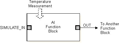
Application example: Traditional Temperature Transmitter
Assume a temperature transmitter is calibrated for a range of 200 to 400°F and is used in a monitor (non-control) application in which accuracy is important. You configure the associated input channel and Analog Input function block as follows.
|
Configuration Setting |
Traditional 4 to 20 mA Transmitter |
HART Transmitter |
|---|---|---|
|
Channel Type |
Analog Input |
HART Analog Input |
|
AI Block IO_IN Parameter |
FIELD_VAL_PCT |
HART_PV |
|
L_TYPE |
Indirect |
Direct |
|
XD_SCALE |
0 to 100% |
200 to 400°F |
|
OUT_SCALE |
200 to 400°F |
200 to 400°F |
The following figure is the function block diagram for this example.
Application Example: RTD / Thermocouple
Assume a 3 wire PT-100 RTD is used to monitor temperature and the required range for the control module is 0 to 110 degrees Fahrenheit. Assume also a type K Thermocouple is used to monitor temperature and the required range for the control module is 10 to 90 degrees Celsius. You configure the associated input channels and Analog Input Function blocks as follows.
|
Configuration Setting |
RTD |
Thermocouple |
|---|---|---|
|
Channel Type |
Pt 100 RTD Input Channel, 3-wire |
Thermocouple_mV, Type K Thermocouple input |
|
AI Block IO_IN Parameter |
FIELD_VAL |
Direct Indep |
|
L_TYPE |
Direct Indep |
Direct Indep |
|
XD_SCALE |
* to °F |
* to °C |
|
OUT_SCALE |
0 to 100°F |
10 to 90°C |
* Note that the XD_SCALE 0% and XD_SCALE 100% values may be left at 0 and 100. However, the XD_SCALE engineering units must be set correctly to either °F or °C (neither 'F' nor 'C' will work correctly). Also the XD_SCALE and OUT_SCALE engineering units must match. When the module is downloaded the actual 0% and 100% values are automatically determined by the channel configuration. For the PT 100 RTD, the XD_SCALE 0% will be set to -328°F and the XD_SCALE 100% will be set to 1562°F. For the Type K Thermocouple, the XD_SCALE 0% will be set to -270 °C and the XD_SCALE 100% will be set to 1372°C.You can observe these values in the online mode of the module.
The following figure is the function block diagram for this example.
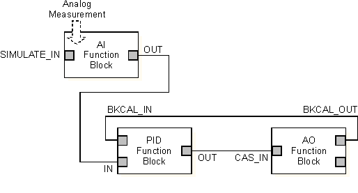
Application example: Traditional Pressure Transmitter
Assume the level of a small open tank is to be measured using a pressure tap near the bottom of the tank. Based on the tap location and the density of the material in the tank, the pressure transmitter is calibrated at 0 to 200 inH2O for a tank level of 0 to 10 ft. The level measurement is used to control the tank level. You configure the associated input channel and Analog Input function block as follows.
|
Configuration Setting |
Traditional 4 to 20 mA Transmitter |
HART Transmitter |
|---|---|---|
|
Channel Type |
Analog Input |
HART Analog Input |
|
AI Block IO_IN Parameter |
FIELD_VAL_PCT |
HART_FIELD_VAL |
|
L_TYPE |
Indirect |
Indirect |
|
XD_SCALE |
0 to 100% |
0 to 200 inH2O |
|
OUT_SCALE |
0 to 10 ft. |
0 to 10 ft. |
The following figure is the function block diagram for this example.
Application example: Traditional Differential Pressure Transmitter
Assume the liquid flow in a line is to be measured using the differential pressure across an orifice plate in the line. Based on the orifice specification sheet, the differential pressure transmitter was calibrated for 0 to 20 inH2O for a flow of 0 to 800 gal/min. The flow measurement is used in a flow control loop. If the transmitter was not set up to take the square root of the differential pressure, you configure the associated input channel and Analog Input function block as follows.
|
Configuration Setting |
Traditional 4 to 20 mA Transmitter |
HART Transmitter |
|---|---|---|
|
Channel Type |
Analog Input |
HART Analog Input |
|
AI Block IO_IN Parameter |
FIELD_VAL_PCT |
HART_FIELD_VAL |
|
L_TYPE |
Indirect Square Root |
Indirect Square Root |
|
XD_SCALE |
0 to 100% |
0 to 20 inH2O |
|
OUT_SCALE |
0 to 800 gal/min |
0 to 800 gal/min |
The function block diagram for this example is identical to the diagram for the previous example.