Function Block Diagrams (FBDs) are comprised of individual Function Blocks and Special Palette Items, such as Input/Output parameters, and Internal read/write parameters. Function block diagrams can also include comments and bitmaps. The following figure shows the display structure of a DeltaV function block.
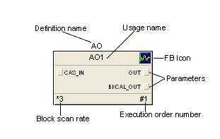
Definition name - the name by which this block is known in the DeltaV Function Block Library.
Usage name - the user defined name for the function block. To rename a function block, select it and right-click, and then click Rename from the context menu.
Function Block Icon - the graphical image used to represent a DeltaV function block.
Parameters - the data used in a function block to perform calculations and logic. The standard connector parameters, which reference the wired inputs and outputs of a function block, appear on the block when it is placed on the diagram from the palette. To show other parameters on the block, right-click, and then click Show Parameters from the context menu.
When copying and pasting several blocks at the same time, select the blocks in their execution order. This ensures that the pasted blocks have the correct execution order. If necessary you can reset the execution order after pasting.
Block scan rate - the number of times the module's algorithm is executed compared to the block. If the scan rate is one (this is the default and does not appear on the block), there is a 1:1 ratio, and every time the module scans, the block executes. If the scan rate is 3, there is a 1:3 ratio, and the block is executed every third scan. To change the scan rate, right-click, and then click Block Scan Rate from the context menu.
Function Block Diagrams are used in the DeltaV system to implement continuously executing control strategies. Every block in the diagram is executed each time the module scans. Graphical wires connect the different blocks within the diagram. Each wire transfers one or more data values from one block to another. The execution order, which you can set, determines when each block of the diagram executes. The following is a picture of a function block diagram.
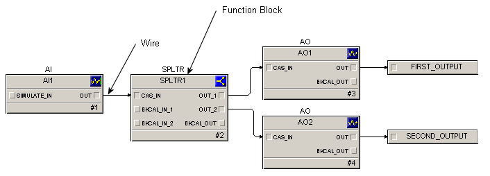
The function blocks within the DeltaV system follow the structure specified by the FOUNDATION fieldbus standard. Additional blocks have been provided to enhance and extend the functionality of the programming language. A set of 46 basic, or primitive, function blocks is available.
Use a function block diagram in Control Studio to create and modify algorithms that are defined with function blocks. Connect the blocks together to define how a module behaves. A standard group of function blocks come with the DeltaV system and are in the Function Block library. Wire these function blocks together to define the module's algorithm.
Including comments and bitmaps
Use the Text and Insert Bitmap commands from the Graphics menu to include comments and bitmaps in function block diagrams. Bitmaps are referenced by function block diagrams. The bitmaps are not included in the function block diagram definition. If you move a module definition to another workstation, you must copy the referenced bitmap to the directory on the target workstation that is the same as the directory on the source workstation.