Rules you must follow
-
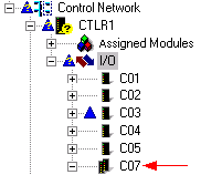
The lower slot number in a redundant pair must be an odd number, and the upper slot number must be the next higher even number. For example, you can install redundant pairs in slots 1 and 2, 3 and 4, and 9 and 10. You cannot install redundant pairs in slots 6 and 7 or 24 and 25. In this example from DeltaV Explorer, the redundant pair, C07, occupies slots 7 and 8. Notice that the next available slot, C06, was not used; this is because the lower slot number in a redundant pair must be odd.
Redundant terminal blocks
-
Other than redundant terminal blocks, no additional software or hardware is required to support redundancy. A redundant terminal block spans two adjacent slots on the I/O carrier. A redundant I/O card consists of two Series 2 cards installed in a redundant terminal block. Both cards access the same set of channels in the terminal block.
-
The double-wide redundant terminal blocks require only a single set of wires for each redundant channel or fieldbus segment. (The exception is the Redundant Interface terminal block that uses two sets of wires for the Series 2 Serial card. One set of wires is for each interface, such as a computer.) The redundant terminal blocks contain screw terminals appropriate for the card type, and signals from the screw terminals are connected to both cards in a redundant pair.
Line fault detection
-
The Series 2 DI, 8-Channel, 24 VDC, Dry Contact and the Series 2 DO, 8-Channel, 24 VDC, High-Side cards support line fault detection. (For DI cards, modify the wiring to include a series and parallel resistor at the sensor.) This capability can be enabled or disabled by configuration changes.
-
After resolving line fault errors, use the Clear Saved Fault Information command in DeltaV Diagnostics to re-enable switchovers if the same problems are detected again.
Manual switchovers