The DeltaV software includes the VLV_DCC_EDC module template. The template is for controlling multi-state discrete devices that require interlocks, permissives, or force setpoints.
This module template is set up for input and output Device Signal Tags. The module template includes configuration tips when viewed in Control Studio.
Use the EDC_PMP_ and EDC_VLV_ dynamos to monitor and control discrete devices that use this module template. The dynamo opens the EDC_fp module faceplate. From the faceplate you can open the EDC_dt detail display for the module and the module's DCC function block faceplate (DCC_fp).
Implementation example
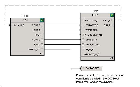
This example uses the Discrete Control Condition function block to configure interlock, permissive, and force setpoint conditions that connect to an EDC function block. The condition outputs of the DCC function block are wired directly to the EDC function block.
- Modify the Quick Config
parameters presented as needed.
- Configure the Device Signal Tag for IO_IN_1, the Close status of the valve (1=CLOSED).
- Configure the Device Signal Tag for IO_IN_2, the Open status of the valve (1=OPEN).
- Configure the Device Signal Tag for IO_OUT_1, the latching output to the valve (1=OPEN).
- To configure to drive to Open when interlocks clear, de-select SP Track in DEVICE_OPTS.
NoteChange STATE_MASKS if it is necessary to invert the inputs or output, or to add or remove states.
- (Optional) Configure IO_OUT_DURATION1 to a value different from 0 to pulse the output for this duration).
- Configure the PASSIVE_STATE as needed.
- Open the properties of the DCC1 function block.
- Add and remove the
interlock conditions as needed. Double click on the condition to configure.
- Configure the interlock expression. The expression should evaluate True to cause an interlock.
- Configure a text description for the condition to appear in the DCC block faceplate.
- (Optional) Set Higher Managed to prevent the condition from being online disabled.
- (Optional) Select Reset Required to latch the output of the interlock condition when it evaluates to True. This requires that the function block be reset to unlatch the interlock condition.
- (Optional) Configure the Delay Off to set the time to elapse before the output of an interlock condition is set to False after the condition clears.
- (Optional) Configure the Delay On to set the time to elapse before the output of an interlock condition to set to True after the condition is detected.
- Add or remove the permissive conditions as needed. Double click on the condition to configure. Configuration of permissive conditions is similar to that of interlock conditions.
- Configure ALGO_OPTS as needed. When Permit is set, configure the permissive expression such that a True evaluation means permit. When Permit is not set, configure the permissive expression such that a True evaluation means prevent.
- Add and remove the force setpoint conditions as needed. Double click on the condition to configure. Configuration of force setpoints is similar to that of permissive conditions.
- Modify the priority of FAIL_ALM from Alarms view if desired.
- Set module properties if desired.
- Modify the History Collection parameters as desired.