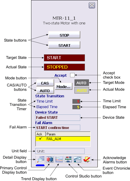
The following items are contained in the faceplate:
-
Permissive Status - When the Permissive option in the DEVICE_OPTS parameter of the Device Control block is set, permissive status is displayed between the Position and Close buttons. When PERMISSIVE_D is True, the word Permit is displayed in green. When False, Permit is displayed in dark red with a No symbol (Ø) overlaid.
-
State buttons - Depending on the type of discrete device being controlled, there are either two or three state buttons, each labeled with a text description of its corresponding state. Click one of these buttons to set the target state (SP_D of the Device Control block) to the state described on the button when the state is permitted.
-
Target State - This area indicates the current target state (SP_D) in white text.
-
Actual State - This area indicates the actual state (PV_D) of the Device Control block in yellow text.
-
Accept check box - This check box is used to toggle the ACCEPT_D parameter in the Device Control block. When Accept is checked, the actual state (PV_D) is set to that of the output state (OUT_D), regardless of the discrete input states that determine FV_D.
-
CAS/AUTO buttons - These buttons are used to set the target mode to the labeled value of CAS or AUTO. The buttons for CAS (not displayed in the figure) and AUTO mode are displayed when CAS is a permitted mode. When CAS is not permitted, neither of these buttons is displayed.
-
Mode button - This button is used to display a list of available target modes. Click one of the permitted modes to set the target mode to that mode. To close the Mode Selector box, click the X button.
-
Target Mode - This field contains a word in white text that describes the target mode for the loop. The background changes to blue when the target mode and normal mode are different.
-
Actual Mode - This field contains a word in yellow text that describes the ACTUAL mode of the loop. The background changes to blue when the actual mode and normal mode are different.
-
State Transition timer - The value shown for Time Limit is the confirm time for the current Setpoint of the Device Control block (for example, CFM_PASS_TIME when SP_D is passive). The Elapsed Time value is the transition timer that begins to increment when the outputs are driven as a result of a change in SP_D.
-
Device State - This field records the current state of the DC_STATE parameter in the Device Control block. When the device state is Locked, a reset button is visible within the text box.
-
Fail Alarm - This field records the current state of the FAIL parameter in the Device Control block.
-
Unit field - This field displays the unit name.
-
Toolbar - Click the icons from left to right to perform the following functions, respectively:
-
Detail Display button: open the detail display for the module.
-
Primary Control Display button: open the primary control display.
-
Trend Display button: open the current trend display for the module.
-
Control Studio button: open Control Studio.
-
Event Chronicle button: open the Process History Viewer.
-
Acknowledge Alarms button: acknowledge all alarms on this module.
-
-
Module Error indicator - A flashing blue bar is displayed below the Detail Display button when a module error occurs. This prompts you to go to the detail display to view and clear the error.