DeltaV CSLS Safety
Instrumented System (SIS)
hardware includes the following:
- DeltaV SIS controllers (model SZ) — SIS controllers connect to the DeltaV Area Control Network (ACN) and isolate the CHARMs Smart Logic Solver from the rest of the system.
- CHARMs Smart Logic Solvers (CSLS) — Connect to the SIS controllers through the Local Safety Network. CSLSs run SIS modules that contain the safety system logic.
- LS CHARMs — The SIS-specific input and output CHARacterizing Modules that bring field signals into the CSLS SIS system.
- Local Safety Network Bridges (LSNBs) — When it is necessary for a CSLS in one Local Safety Network (LSN) to communicate secure data to a CSLS in another LSN, two or more LSNs can be connected with LSNBs to form a Global Safety Network (GSN).
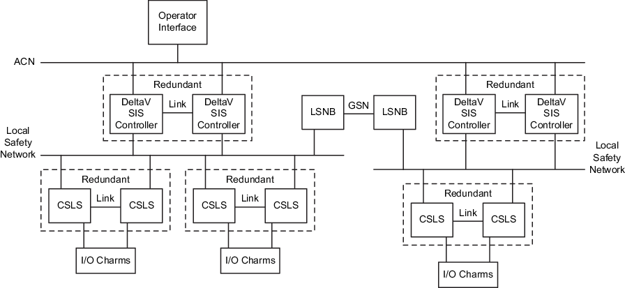
The following figure shows a schematic diagram of an example CSLS system implementation. The schematic shows two redundant SIS Controllers, each with its Local Safety Network. One of the networks has two redundant CSLSs and the other has one redundant CSLS. The two Local Safety Networks are connected by Local Safety Network Bridges to form a Global Safety Network.
Note
The SIS Controller and CSLS can be installed as simplex but the carriers support redundancy so there is no impact on the hardware footprint to do so.