The module template is fairly simple, consisting of only one function block. To customize the module for the tank application, all you need to do is identify the Device Signal Tags for the input and output. (Device Tags are assigned to the I/O channels as part of the I/O card configuration process.)
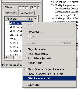
- Select and right-click a parameter in the Parameter view, and then select Filter Parameter List.
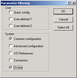
- In the System group, select Common configuration to display the parameters most commonly used for configuring process control, and select On-line to display the parameters most commonly used for operating a process.
-
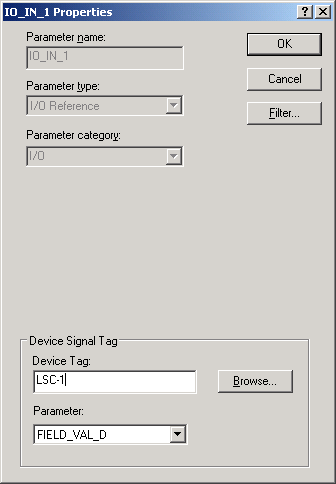
In the
Device Tag field, enter LSC-1. (LSC-1 is the
Device Tag used in our tank example for Limit Switch-Closed.)
The Device Tags for the tank application are listed in the table in Control modules used in the tutorials.
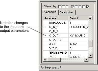
The IO_IN_1 parameter is given a value of FIELD_VAL_D. (You can click the Parameter field to see this value. It also appears in the Parameter view.) LSC-1, together with the FIELD_VAL_D parameter define the Device Signal Tag (DST).
(If you have configured placeholders for the I/O cards, you can browse for the Device Tags. Clicking the Browse button opens a dialog that lists all the configured I/O card channels and their assigned Device Tags. You can scroll down the list, select the appropriate Device Tag, and then click OK. Click the Alphabetic tab to alphabetize the list and scroll past the entries beginning with COxx to get to the Device Tag names such as LSC-1.)
- In the Device Tag field, enter XV-1, and then click OK.