Fiber star network for multiple buildings with DeltaV Smart Switches, distributed controllers, and CHARMs I/O

Note

The images in this topic show an example connection scheme; many other connection schemes are possible. For example, it is possible to have a star network from a 24 port twisted pair switch to 24 buildings (not to exceed the DeltaV system capacities). There are many combinations of star networks possible using a mixture of fiber-optic cable that is required for outdoor cable runs and twisted pair cable for indoor floor-to- floor or area-to-area runs. The network shown in the images physically supports 11,520 CHARMs due to the number of cabinets and CIOCs shown; however, many more CHARMs are possible on a single network with additional CIOCs and controllers located across the plant either in cabinets or field enclosures or mounted on DIN rails in a standalone application. Refer to the System Capacities topic for the supported ratio of CHARMs-to-CIOCs-to controllers. In the image, notice that a single controller is located in each building and several controllers are located in the control room. Because approximately 1,440 CHARMs are located in each building in this example and controllers support up to 1500 DSTs, it is convenient and very secure to locate the controller to which the CHARMs are assigned in the same building on the same side of the external fiber-optic links. Controllers can be located anywhere on the network as long as the rules for the ratio of CHARMs-to-CIOCs-to-controllers are followed.

The following image shows a top-down view of a network distributed between eight buildings. Figure: Detailed view of the connections within each building shows details on the connections within each building.
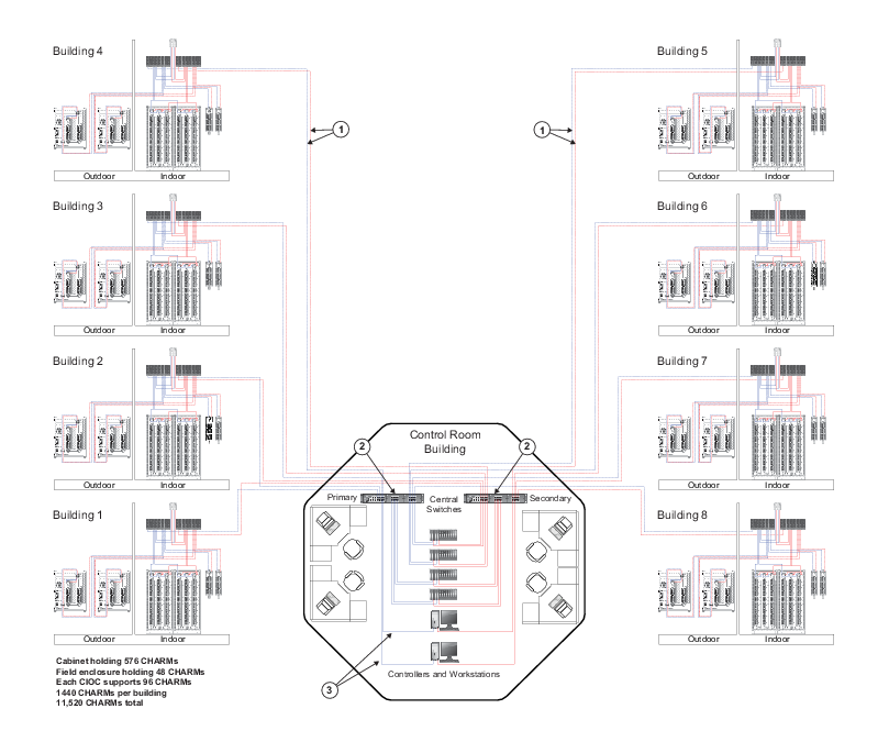
Figure: DeltaV Smart Switches, distributed controllers, and CHARMs I/O in a fiber-optic star network


Callout Description
Fiber-optic cable must be used for outdoor building-to-building communications for immunity from electromagnetic interference caused by near lightning strikes; for ground isolation between buildings; and to gain additional distance that goes beyond the 100 meters (328 ft) maximum allowed for screened twisted pair cabling (ScTP). Both single-mode and multimode fiber-optic cable can be used with the appropriate DeltaV Smart Switches but only multimode fiber-optic cable can be used with the fiber-optic I/O Port (IOP) on the CIOC Carrier.
The DeltaV RM100 Smart Switch is shown here ; however, there are other Smart Switch types that could be used depending on the number of ports and cable media types needed for each connection. The DeltaV RM100 Smart Switch shown here is the modular version that is initially equipped with eight (8), fixed twisted pair 10/100mb/s ports and two blank panels. The blank panels can be removed and 8-port, hot-swappable, multimode and single-mode fiber-optic expansion modules can be installed for these building-to-building fiber- optic connections. Multimode fiber-optic cable only can be used with the fiber-optic I/O Port (IOP) on the CIOC Carrier.
This is a 100 meter (maximum) straight-through or crossover cable. To prevent ground loops, build this cable assembly with a shielded, metal-enclosed RJ45 connector on one end and an isolated, plastic-enclosed RJ45 connector on the other end. The metal connector end of this cable assembly must be placed on the switch and not on the PC.
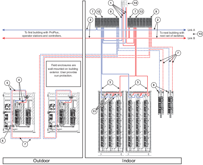
Figure: Detailed view of the connections within each building


Callout Description
100 m (max) straight-through or crossover cable. The shield on the controller's RJ45 connector connects only to a Faraday cage in the controller; not to the controller's DC ground. Therefore, the RJ45 connectors are floating and the single point of ground is made at the switch to which the controller is connected. Build this cable assembly with a shielded, metal-enclosed RJ45 connector on both ends.
100 m (max) straight-through or crossover cable. To prevent ground loops, build this cable assembly with a shielded, metal-enclosed RJ45 connector on one end and an isolated, plastic-enclosed RJ45 connector on the other end. The metal connector end of this cable must be placed on the switch and not on the PC.
For the 288 CHARM cabinet shown in this image, the primary control network connects to CIOC1 located in the front left of the cabinet and the secondary control network connects to CIOC3 located in the front right of the cabinet. For the 576 CHARM cabinet, the secondary control network connects to CIOC6 located in the back right of the cabinet. The cascade (daisy-chained) connections between the connections are prewired with 100 m (maximum) straight-through or crossover cable. The shield on the CIOC's RJ45 connector connects only to a Faraday cage in the CIOC; not to the CIOC's DC ground. Therefore, the RJ45 connectors are floating and the single point of ground is made at the switch to which the CIOC is connected. Build this cable assembly with a shielded, metal-enclosed RJ45 connector on both ends.
Factory installed Cat 5e ScTP (shielded) communications cable.
Factory installed multimode fiber-optic cable.
Fiber-optic network adapter. Connections to an internal redundant fiber-optic network are made through this patch panel. The incoming external fibers must be terminated with SC connectors. The patch panel consists of:
  • Two DIN rail-mounted, duplex SC-SC adapters. Each duplex adapter receives two SC-terminated fibers: one fiber is for incoming, receive data and the other fiber is for outgoing transmit data. One duplex adapter is for the primary DeltaV control network and the other is for the secondary DeltaV control network.
  • Two additional, duplex SC-SC adapters. The SC-SC adapters are compatible with the following types of fiber-optic cable:
    • Multimode (MM) in 62.5/125 micron core/cladding diameters (OM1)
    • Multimode (MM) in 50/125 micron core/cladding diameters (OM2)
The DeltaV MD30 Smart Switch is shown for reference. Other Smart Switch types could be used depending upon the number of ports and cable media types needed for each connection. The MD30 Smart Switch contains an extra module with two fiber-optic SFP slots (used for optional SFP fiber-optic transceiver modules) and two twisted pair 10/100/1000 mb/s uplinks. Up to two of the four ports on this module can be used simultaneously in any combination of fiber and twisted pair.
The CIOC with a multimode fiber-optic network interface (MTRJ port), is an edge device for an end-of-line group of remotely located CHARMs I/O. CIOCs with a fiber-optic network interface cannot be daisy-chained and are used for star-connected CHARMs networks as shown in the image. The fiber-optic MTRJ port is for use with multimode fiber-optic cable with diameters of 62.5/125 or 50.125 μm. The maximum distance supported is in the 2 kilometer range; however, the actual distance supported is influenced by the number and quality of fiber-optic splices, patch panels, and grade and attenuation of the fiber-optic cable. Refer to the CIOC Carrier specifications for the fiber-optic link budget. Single mode fiber-optic cable is not supported. For single mode fiber applications, a low port number, external fiber-optic switch can be used to link the twisted-pair version of the CIOC using fiber-optic cable. Refer to the DeltaV Smart Switch Product Data Sheets for more information.
Multimode fiber-optic modules for the DeltaV 24 VDC powered rail-mounted Smart Switches. DeltaV Smart Switches with other form factors such as the 19 inch AC powered rack mounted switches and the fixed port 24 VDC rail-mounted switches are also available with multimode fiber-optic ports.
The redundant controller could be located on different switches near the control room in a different building or located as shown here with its CIOC/CHARMs hardware. There can be up to 12 switches daisy-chained between CIOC/CHARMs hardware and the controllers they communicate with when all are on the same side of the firewall. Do not place a firewall between the CIOC/CHARMs and their associated controllers. Controllers and CIOCs must reside on the same DeltaV network, not separated by firewalls or routers. Up to eight controllers and many CIOCs can be placed on the protected side of a DeltaV Controller Firewall. A preferred method of connecting other buildings/areas to the main control room Ethernet switch is to use a network star so that each leg of the star supports one remote area or building. Using a star topology is generally preferred by maintenance personnel because they know that if they are working on one leg of a star and power is removed from that area the communication chain would not be broken.
Factory installed cascade (daisy-chained) connections between the CIOCs are Cat 5e ScTP (shielded) communications cable.
Twisted pair module (4 port) for the DeltaV 24 VDC powered rail-mounted switches. DeltaV Smart Switches with other form factors such as 19 inch rack-mounted switches and the fixed port 24 VDC rail-mounted switches are also available with twisted pair ports.
Rather than continue to the next building in a daisy-chain, the preferred method is to end the link in this building and implement it as one leg of a star (eliminating link A and link B).