| Channel type
|
RTD input
|
| Sensor types
|
Refer to
Table: RTD Sensor type specifications
|
| Sensor configuration
|
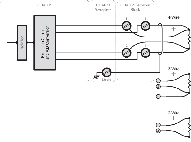
2, 3, or 4-wire
|
| Full scale signal range
|
Selectable based on sensor. Refer to
Table: RTD Sensor type specifications
|
| Accuracy over full temperature range
|
Depends upon the sensor type. Refer to the
temperature drift specification in
Table: RTD Sensor type specifications
|
| Repeatability
|
0.05% of span
|
| Resolution
|
Depends upon the sensor type. Refer to the
resolution specification in
Table: RTD Sensor type specifications
|
| Calibration
|
None required
|
| Sensor excitation current
|
- 0.5 mA in 2 and
4-wire configurations
- 0.25 mA in 3-wire
configurations
|
| DC50/60 Hz common mode rejection
|
90 dB typical
|
| Channel isolation
|
RTD sensor input is galvanically isolated and
factory tested to 1000 VDC.
|
| Open sensor detection
|
Yes
|
| Input power requirements
|
Total power requirement: +24 VDC ±10% at 22
mA maximum :
- Input power from
CIOC: +6.3 VDC ±3% at 32 mA maximum
- +24 VDC input
power: ±10% at 10 mA maximum
|
| CHARM heat dissipation
|
0.30 W
|