The System Power Supply (AC/DC) converts AC input power to 12 VDC for the I/O subsystem (I/O power is expressed as LocalBus power in the power calculation worksheets). In addition, it converts some input power to supply the requirements of the controller if it is mounted directly to the left of the controller or on the right slot of a second 2-wide power/controller carrier.
The left slot of the second 2-wide power/controller carrier will NOT provide power to the controller, only to the I/O subsystem.
Supplying System Power to the I/O
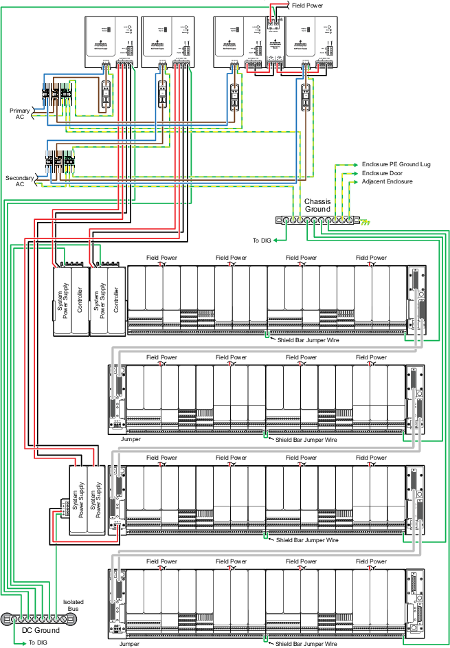
For some system sizes, I/O power requirements cannot be met by a single supply. In these cases, you must use multiple supplies for load sharing. By adding a second system power supply (or more) and additional carriers, you can increase the power available for the I/O. You may need as many as four supplies for a full system of analog I/O cards.
For load sharing, mount the second supply in either slot of the second power/controller carrier. Additional supplies mount to the left of the second supply or on a third power/controller carrier, if needed. The following figure shows an example of four system power supplies used for load sharing.
In an application requiring redundant power to the controller rather than load sharing, the second system power supply in Figure J-1 would provide only 15 W to the I/O and 10 W to the controller. Refer to “Supplying Redundant System Power to the Controller”. Refer also to Table: LocalBus Current Provided to the I/O for information on LocalBus current provided to the I/O in various controller/power redundancy situations.
Extending System Power to the I/O
The LocalBus power is specified and limited to 8 A. Some cards consume up to 0.5 A of system power each. Because of this, a system with several cards such as AS-Interface, Profibus, DeviceNet, and Fieldbus cards can exceed the ratings.
The 8-wide carriers must be left-aligned when using 1-wide extenders.
The following image shows power injected for two system power supplies mounted on the 2-Wide Horizontal Power Carrier. The power is supplied to the left 1-Wide Horizontal Carrier Extender positive and negative (+ and -) screw terminals with the jumper removed. In addition to supplying DC power, the system power supplies on the 2-Wide Horizontal Carrier provide additional filtering for the local extended railbus.
Supplying Redundant System Power to the Controller
To provide redundant power to the controller, install a secondary system power supply in the right slot of the second power/controller carrier, as shown in the following figure. You must mount the secondary supply in the right slot of the second carrier to provide power to the controller.
If you require redundant power to the controller and additional system power supplies for I/O load sharing, you must mount the secondary system power supply for the controller in the right slot of the second carrier, as shown in Figure J-3.
LocalBus Current Provided to the I/O Based on Controller/Power Redundancy
The following table shows the LocalBus current provided to the I/O based on the number of System Power Supplies (AC/DC) and the controller/power redundancy used in the configuration.
| Number of System Power Supplies (AC/DC) | Controller/Power Redundancy | ||
|---|---|---|---|
| Simplex Controller and Simplex Power | Simplex Controller and Redundant Power | Redundant Controller and Redundant Power | |
| 1 | 1.25 A | N/A | N/A |
| 2 | 3.35 A | 1.25 A | 1.25 A |
| 3 | 5.45 A | 3.35 A | 2.50 A |
| 4 | 7.55 A | 5.45 A | 4.6 A |
| 5 | 9.65 A; current limited to 8.0 A due to carrier limitations | 7.55 A | 6.7 A |
| 6 | 11.75 A; current limited to 8.0 A due to carrier limitations | 9.65 A; current limited to 8.0 A due to carrier limitations | 8.8 A; current limited to 8.0 A due to carrier limitations |