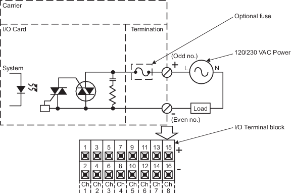
| Number of channels
|
Eight
|
| Isolation
|
Each channel is optically isolated from the
system at 250 VAC and from other channels at 250 VAC.
|
| Output range
|
20 VAC to 250 VAC
|
| Output rating
|
- 1.0 A continuous
per channel (inrush 5 A for <100 ms; 20 A for <20 ms)
- 3.0 A maximum per
card up to 50°C (122°F)
- 2.0 A maximum per
card up to 60°C (140°F)
Series 2:
-
1.0 A continuous per channel (inrush 5 A for <100 ms;
20 A for <20 ms)
-
3.0 A maximum per card
|
| Optional fuse
|
2.0 A (inrush 5A for <10 ms at 0.1% duty
cycle)
|
| Off state leakage
|
- 2 mA maximum at
120 VAC
- 4 mA maximum at
230 VAC
|
| LocalBus current (12 VDC nominal), per card
|
- 100 mA typical
- 150 mA maximum
|
| Field circuit power, per card
|
None
|
| Configurable
channel types:
|
| Discrete Output
|
- If
FAIL_ACTION_MODE is Hold last value (default): Output stays in last state
submitted by the controller.
- If
FAIL_ACTION_MODE is Go to configured failure action mode: Output is driven to
the configured faultstate value.
|
| Momentary Output
|
- If
FAIL_ACTION_MODE is Hold last value (default): Output finishes current pulse.
- If
FAIL_ACTION_MODE is Go to configured failure action mode: Output is driven to
the configured faultstate value and the channel is re-configured as a latched
output.
|
| Continuous Pulse Output
|
- If
FAIL_ACTION_MODE is Hold last value (default): Output continues pulsing.
- If
FAIL_ACTION_MODE is Go to configured failure action mode: Output is driven to
the configured faultstate value and the channel is re-configured as a latched
output.
|
| Mounting
|
Assigned slot of I/O carrier
|