|
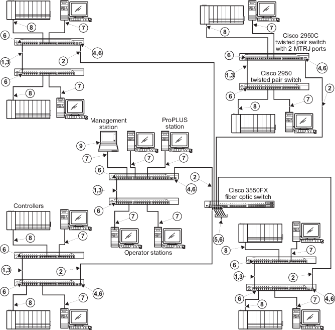
100 m (max) crossover cable. Cat. 5e
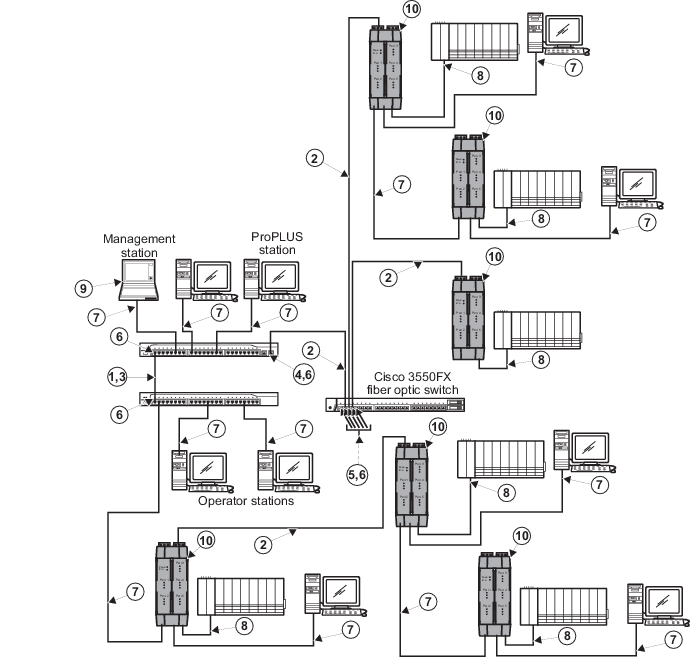
Screened Twisted Pair crossover cable (transmit and receive) is required
between switches.
|

|
2 km (max) full duplex Multimode Fiber
with MTRJ Connectors.
|

|
To prevent ground loops, build this cable
assembly with a shielded, metal-enclosed RJ45 connector on one end and an
isolated, plastic-enclosed RJ45 connector on the other end. The metal connector
end of this cable assembly/link can be placed on either switch.
|

|
The two MTRJ ports on this switch are set
by Cisco to 100BASE-FX full duplex operation. Neither the speed nor duplex can
be changed. Ensure that any devices attached to these ports are properly
configured for 100BASE-FX full duplex operation
before making the connection.
|

|
All ports have been preconfigured by
Emerson Process Management to 100BASE-FX full duplex operation in order to meet
the most typical network configuration requirements. It is good practice to
check each port's duplex setting before connecting to them since it is possible
to configure each of these ports to half duplex operation. Half duplex
operation is not recommended when using switch-to-switch connections as shown
in the preceding figure
. A duplex mismatch can cause serious communications
problems.
|

|
If switch management is to be used over
the network via telnet or a web browser, be aware that access privileges and
port configuration requirements exist for both fiber-optic and twisted pair
switch-to-switch links. Refer to
Managing Cisco Switches in Books Online for
information. Refer to the Cisco documentation for web management information. A
dedicated non-DeltaV PC is required for switch management. Use an IP address
from the address range allowed for switches for this PC.
|

|
100 m (max) straight-through cable. To
prevent ground loops, build this cable assembly with a shielded, metal-enclosed
RJ45 connector on one end and an isolated, plastic-enclosed RJ45 connector on
the other end. The metal connector end of this cable assembly/link must be
placed on the switch and not on the PC.
|

|
100 m (max) straight-through cable. The
shield on the controller's RJ45 connector connects only to a Faraday cage in
the controller; not to the controller's DC ground. Therefore, the RJ45
connectors are floating and the single point of ground is made at the hub or
switch to which the controller is connected. Build this cable assembly with a
shielded, metal-enclosed RJ45 connector on
both ends .
|

|
The Management station has special
hardware and software requirements. Refer to the information on the management
station in the related topics before connecting the station to the DeltaV
Control Network.
|

|
The cable shields connected to the Single
Port Fiber Switch must be grounded. To ground the shields, connect the shield
GND to ground or use a twisted pair cable with both shield ends connected and
installed in a grounded port.
|