|
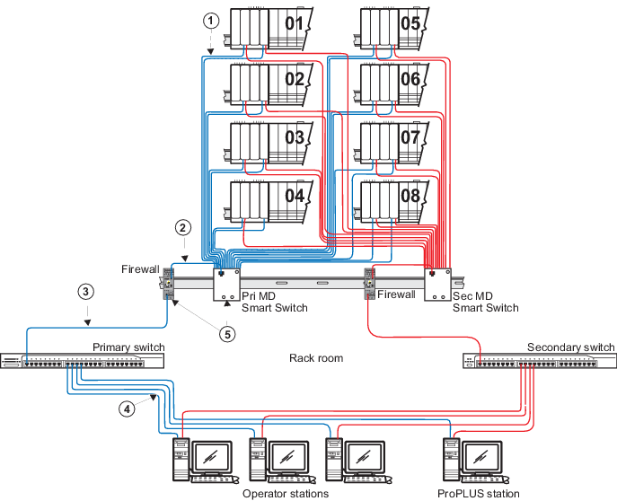
100 m (max) straight-through Category 5e
Screened Twisted Pair (ScTP) cable. The shield on the controller's RJ45
connector connects only to a Faraday cage in the controller; not to the
controller's DC ground. Therefore, the RJ45 connectors are floating and the
single point of ground is made at the switch to which the controller is
connected. Build this cable assembly with a shielded, metal-enclosed RJ45
connector on both ends.
|

|
100 m (max) straight-through ScTP cable.
To prevent ground loops, build this cable assembly with a shielded,
metal-enclosed RJ45 connector on one end and an isolated, plastic-enclosed RJ45
connector on the other end. The metal connector end of this cable assembly/link
must be placed on the mini-switch and not on the firewall IPD port.
|

|
100 m (max) straight-through ScTP cable.
To prevent ground loops, build this cable assembly with a shielded,
metal-enclosed RJ45 connector on one end and an isolated, plastic-enclosed RJ45
connector on the other end. The metal connector end of this cable assembly/link
must be placed on the rack room switch and not on the firewall IPD port.
|

|
100 m (max) straight-through ScTP cable.
To prevent ground loops, build this cable assembly with a shielded,
metal-enclosed RJ45 connector on one end and an isolated, plastic-enclosed RJ45
connector on the other end. The metal connector end of this cable assembly/link
must be placed on the rack room switch and not on the workstation.
|

|
Attach a separate ground wire to the front
panel screw that is labeled with the ground symbol and connect this wire to a
suitable instrumentation ground.
|