|
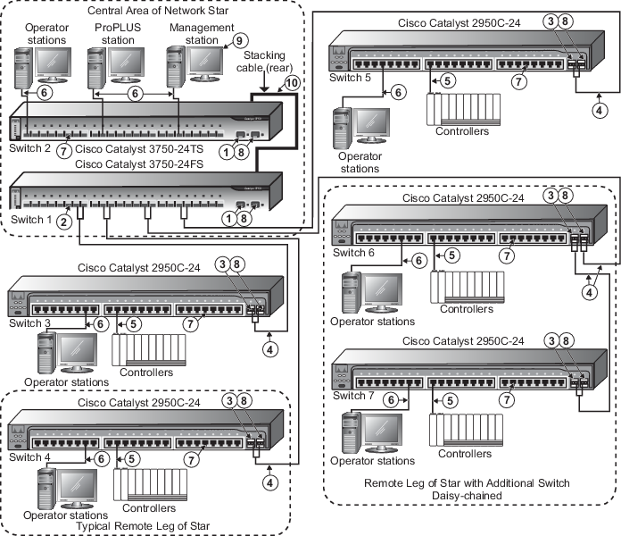
The SFP slots (not used in the preceding
image ) can be fitted with any combination of the SX or LH fiber-optic
transceiver modules. The SX module supports up to 550 meters of Multimode Fiber
and the LH module supports up to 10 kilometers of Single Mode Fiber.
Fiber-optic splices, patch panels, and connector losses reduce these overall
distances. The SFP slots and transceivers operate at 1000Mb (gigabit) full
duplex only.
|

|
All MTRJ fiber-optic ports on this switch
have been preconfigured by Emerson to 100BASE-FX full duplex
operation in order to meet the most typical network configuration requirements.
It is good practice to check each port's duplex setting before connecting to
them since it is also possible to configure each of these ports to half duplex
operation. Half duplex operation is not recommended for switch-to-switch
connections. Check both ends of the link and ensure that they are both
configured to full duplex operation or a duplex mismatch, which can cause
serious communications problems, could occur.
|

|
The two MTRJ ports on this switch are set
by Cisco to 100BASE-FX full duplex operation. Neither the speed nor duplex can
be changed. Ensure that all devices attached to these ports are properly
configured for 100BASE-FX full duplex operation
before making the connection.
|

|
2 km (max) full duplex Mulimode Fiber with
MTRJ connectors.
|

|
100 m (max) straight-through cable. The
shield on the controller's RJ45 connector connects only to a Faraday cage in
the controller; not to the controller's DC ground. Therefore, the RJ45
connectors are floating and the single point of ground is made at the hub or
switch to which the controller is connected. Build this cable assembly with a
shielded, metal-enclosed RJ45 connector on
both ends .
|

|
100 m (max) straight-through cable. To
prevent ground loops, build this cable assembly with a shielded, metal-enclosed
RJ45 connector on one end and an isolated, plastic-enclosed RJ45 connector on
the other end. The metal connector end of this cable assembly/link
must be placed on the switch and
not on the PC.
|

|
All twisted pair ports are configured to
auto-sense speed and auto-negotiate duplex. Do not hard-configure speed or
duplex on the twisted pair switch ports or duplex mismatches, which create
communications failures, will occur. Always allow the switch to auto-sense
speed and auto-negotiate duplex.
|

|
If switch management is to be used over
the network via telnet or a web browser, be aware that access privileges and
port configuration requirements exist for the switch-to-switch links. Refer to
"Managing Cisco Switches" in Books Online for information. Refer to the list of
reserved IP addresses that are allowed for switches on DeltaV systems. Refer to
the Cisco documentation for web management information. A dedicated non-DeltaV
PC is required for switch management.
|

|
The Management station has special
hardware and software requirements. Refer to the related topics for information
on the management station before connecting the station to the DeltaV Control
Network.
|

|
A Cisco stacking cable is included with
the switch and can be used to connect two 3750-series switches together to form
a single switch that can be managed with one IP address.
|