The system power supply takes line power or power from a bulk power supply and converts it to 12 VDC power to drive the controller and I/O cards. The system power supply mounts on either slot of the 2-wide power/controller carrier. For mounting on a 4-wide power/controller carrier refer to Appendix M DeltaV Vertical Carriers.
This section describes the connections for a simplex system power supply. Refer to Appendix E System Power Supply Specifications for system power supply specifications and for details on redundancy.
Refer to the figures following the steps for more information.
-
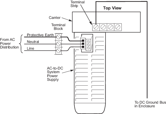
Connect the input supply wires to the input power connection on
the top of the system power supply. Figure 2-15 shows input supply wiring for
the system power supply (AC/DC).
Figure: Simplex Wiring Diagram for System Power Supply
(AC/DC)
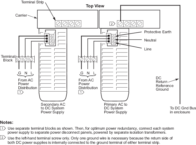
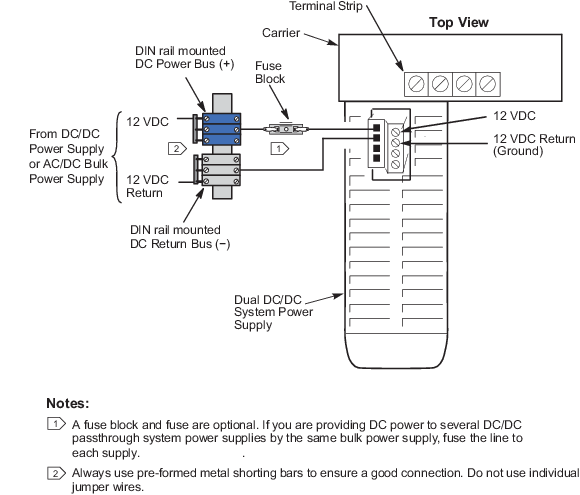
shows the input supply wiring for the system power supply (Dual DC/DC). If you
have secondary system power supplies, connect the input supply drops to each
system power supply as shown in Appendix E System Power Supply Specifications.
 WARNING!
Always remove input power to the supply before connecting or disconnecting the input power connection. The connector should not interrupt current flow and could be damaged if actuated under a load condition. Refer to Appendix J Power Guidelines for more information.
NoteIf you are using a Two-Wide Power Carrier and redundant AC-to-DC power supplies, connect only one of the power supplies to protective earth.
Refer to Appendix J Power Guidelines for power supply and grounding overviews.
-
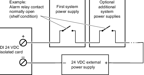
Install alarm contact wiring as shown in the following figure.
Note
The alarm relay contact is closed during normal operation. The alarm relay is shown open (unpowered condition) in the following figure.
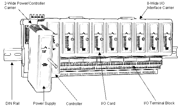
- Align the system power supply with the connector on the 2-wide power/controller carrier and push to attach, as shown in the following figure. Tighten the mounting screw.