Installation notes
The DeltaV system supports the LS DO 24 VDC DTA CHARM, the LS DO 24 VDC (Redundant DTA) CHARM, the LS DO 24 VDC ETA CHARM, and the LS DO 24 VDC (Redundant ETA) CHARM.
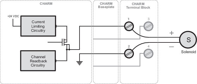
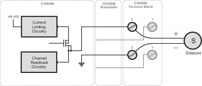
- The LS DO 24 VDC DTA CHARM requires the CHARM Terminal Block. This CHARM is suitable for use in SIL 3 de-energize to trip (DTA) applications.
- The LS DO 24 VDC ETA CHARM requires the CHARM Terminal Block. This CHARM is suitable for use in SIL 3 energize to trip (ETA) applications when deployed with a hardware fault tolerance of 1 (either redundant CHARM or redundant field elements).
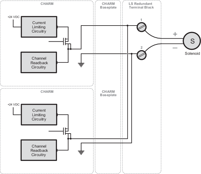
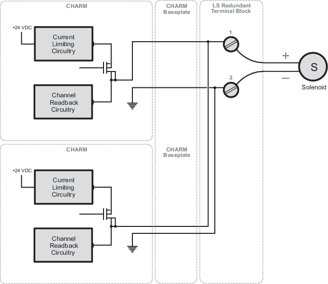
- The LS DO 24 VDC
(Redundant DTA) CHARM can use the following terminal blocks:
- The LS Redundant Terminal Block
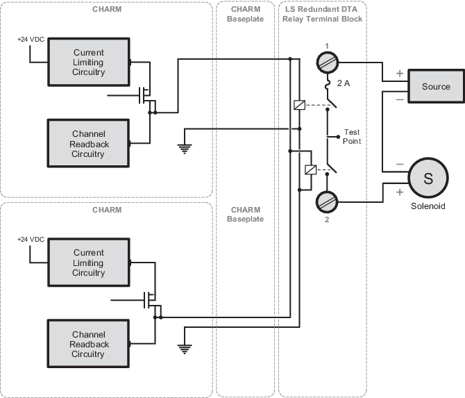
- For applications that drive a final element that requires more than 500 mA use the LS Redundant DTA Relay Terminal Block. The LS Redundant DTA Relay Terminal Block has a built-in relay that can handle up to 1 A and the redundancy allows for higher safety coverage to shut down the process.
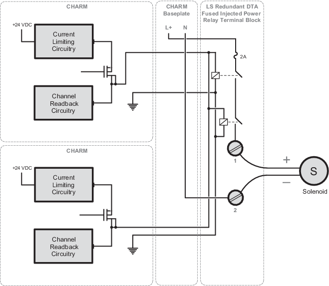
- For applications that drive a final element that requires more than 500 mA, and also requires the use of the baseplate's injected power bus rather than system power, use the LS Redundant DTA Fused Injected Power Relay Terminal Block. The LS Redundant DTA Fused Injected Power Relay Terminal Block has a built-in relay that can handle up to 1 A and the redundancy allows for higher safety coverage to shut down the process.
- This CHARM is suitable for use in SIL 3 de-energize to trip (DTA) applications.
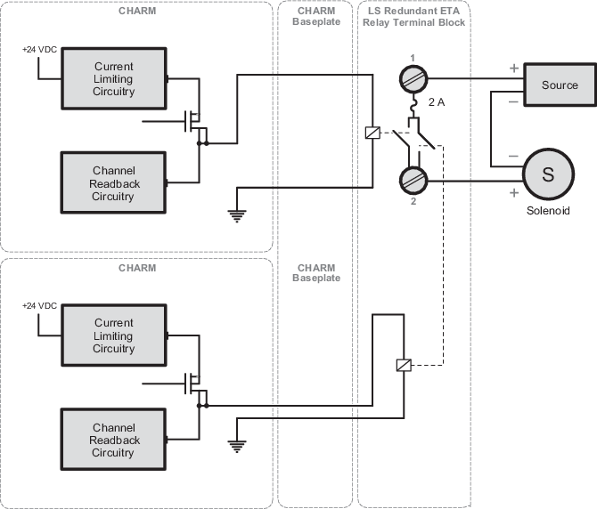
- The LS DO 24 VDC (Redundant ETA) CHARM requires the LS Redundant Terminal Block or the LS Redundant ETA Relay Terminal Block. This CHARM is suitable for use in SIL 2 energize to trip (ETA) applications.
- The LS DO CHARMs have
short circuit protection and support line monitoring for sensing field wiring
faults such as open and short circuits. Line monitoring is enabled in the
configuration.
Note
Line fault detection is not compatible with significant capacitive loading (cable + load > 30 nF) and must be disabled under these conditions.