The following figure shows the detail display in DeltaV Operate's run mode and describes the gain scheduling parameters. In order to minimize controller CPU loading, it takes about ten module scans to fully reflect the change of some of the configuration parameters. However, the actual GAIN, RESET, and RATE are calculated and written to the PID block every scan.
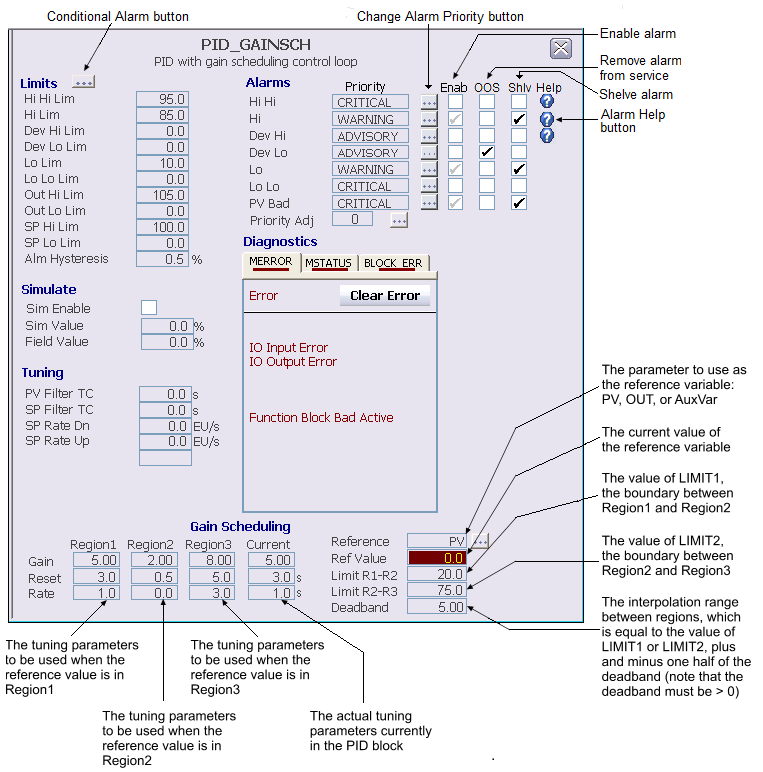
In the preceding figure, LIMIT R1-R2 (LIMIT1) is 25, LIMIT R2-R3 (LIMIT2) is 75, and DEADBAND is 6. That means the Region 1 settings are used as the actual settings whenever the PV of the PID block is 22 or less. When the PV is between 22 and 28, a linear interpolation between the Region 1 and Region 2 settings are used to calculate the actual settings. Similarly, Region 2 settings are used when the PV is between 28 and 72, a linear interpolation is done when the PV is between 72 and 78, and Region 3 settings are used above 78.
Enter values for the GAIN, RESET, and RATE in each of the regions. As the tuning procedure takes place, be sure that the reference variable remains within the particular region during the process identification step.