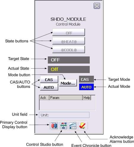
The following items are contained in the faceplate:
-
State buttons - Depending on the type of discrete device being controlled, there are either two or three state buttons, each labeled with a text description of its corresponding state. Click one of these buttons to set the target state to the state described on the button when the state is permitted.
-
Target State - This area indicates the current target state in white text.
-
Actual State - This area indicates the actual state in yellow text.
-
CAS/AUTO buttons - Use the buttons to set the target mode to the labeled value of CAS or AUTO. The buttons for CAS and AUTO mode are displayed when CAS is a permitted mode. When CAS is not permitted, neither of these buttons is displayed.
-
Mode button - Use this button to display a list of available target modes. Click one of the permitted modes to set the target mode to that mode. To close the Mode Selector box, click the X button.
-
Target Mode - This field contains a word in white text that names the target mode. The background changes to blue when the target mode and normal mode are different.
-
Actual Mode - This field contains a word in yellow text that names the current mode. The background changes to blue when the actual mode and normal mode are different.
-
Unit field - This field displays the unit name.
-
Toolbar - Click the icons from left to right to perform the following functions, respectively: