There are a number of things to configure to control the behavior of an EDC block.
Configuring the Passive state
To define the Passive state, configure the PASSIVE_STATE parameter (Named Set) to one of the six supported states (State 0 through State 5). The other five states are the active states.
The Passive state is configured in the PASSIVE_STATE parameter (Named Set) to one of the six supported states (State 0 through State 5), and the other states are the Active states. For example, if State 1 is the Passive state and SHUTDOWN_D is True, the device is forced to State 1. The Passive state can be configured only to an enabled state.
The SP_D and PASSIVE_STATE parameters can be one of the six following states
| Value | State |
|---|---|
|
0 |
State 0 |
|
1 |
State 1 |
|
2 |
State 2 |
|
3 |
State 3 |
|
4 |
State 4 |
|
5 |
State 5 |
You can use the default named sets or create your own.
Inputs/Outputs
An italic n (n) following a parameter name indicates there are multiple instances of the parameter. For example IO_IN_n represents IO_IN_1, IO_IN_2 and so on. The number of parameters available is stated in the parameter table for the block.
The EDC block allows as many as four feedback signals and four output signals associated with the discrete field device. The eight input/output signals are referenced by the EDC block through the I/O parameters. The IO_IN_n parameters reference the discrete feedback signals coming from the field device. The IO_OUTn parameters reference the discrete output signals that command the field device to a requested state.
The feedback input IO_IN_n discrete signal values and statuses are stored in the internal parameters F_IN_Dn . These signal values are used for FV_D state determination.
The F_IN_Dn parameters can be exposed and wired to instead of the corresponding IO_IN_n parameters to connect module-level parameters into the PV_D of an EDC block. For a PV_D that is derived from a combination of DST signals and module parameters, we recommend using DI blocks to read the DST signals into the module and wire all signals to the F_IN_Dn parameters of the EDC Block. If IO_IN_n parameters are used with F_IN_Dn parameters, you must configure the DST signals starting at IO_IN_1, IO_IN_2, and so forth, and use the remaining inputs for the F_IN_Dn parameters.
An EDC block with the BAD_MASK Output Failure option selected sets the BAD_ACTIVE flag on output failure only if the associated I/O channel was at one time enabled, and then disabled, and then only the I/O card is downloaded.
The requested state (stored in OUT_D) is decoded to the individual IO_OUT_n channel outputs according to the corresponding output state mask. The value and status of the IO_OUT_n channels are read back and copied to the internal parameters F_OUT_Dn to track the output channel values and to calculate the status of OUT_D.
The IO_OUT_n discrete output channel values are determined from the output mask that corresponds to the current state stored in OUT_D. Likewise, the block uses the IO_IN_n discrete input channel values to find a matching input mask to determine the state stored in FV_D and PV_D.
The STATE_MASKS parameter defines the output and input combinations of IO_OUT_n and IO_IN_n for each of the six different states that can be contained in the parameters SP_D, OUT_D, FV_D and PV_D. An Undefined state means the IO_IN_n references do not match any of the defined input STATE_MASKS.
Enter the expected/desired values of inputs and outputs for each of six states in the boxes in the State Masks dialog. A blank box indicates a False (0) input or output value. A box with a check mark indicates a True (1) input or output value. Gray boxes indicate inputs and outputs that are not used or do not matter.
The following figure shows a simple state masks configuration example.
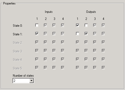
In this example, if IO_IN_1 is True (1), the FV_D parameter value is 1, indicating the State 1. When the block sets OUT_D to a value of 1 to request the State 1, the State 1 output mask sets IO_OUT_1 to 0 and IO_OUT_2 to 1.
Use the dropdown box to indicate the number of states used. This determines which states are considered when matching bit patterns. By default, no optional state is selected. Only state 0 and state 1 are mandatory.
The following figure shows an example definition of the State 0, State 1, and State 2 bit masks for a group of input and output I/O parameters.
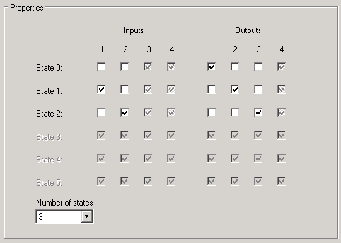
The grayed out output settings are always set to False
Device options
The device options settings affect how the EDC logic is evaluated. The following table presents the available device options and how they affect the EDC logic.
| Bit | Option | Description |
|---|---|---|
|
15 |
Interlock |
If Interlock is selected, SHUTDOWN_D is False, and the INTERLOCK_D input is False, OUT_D is set to the INTERLOCK_STATE and held there until INTERLOCK_D is set back to True or SHUTDOWN_D becomes True. |
|
14 |
SP Track on Shutdown/Interlock |
SP Track on Shutdown/Interlock causes SP_D to track OUT_D. If SP Track on Shutdown/Interlock is selected and OPERATION_STATE is Shutdown or Interlocked, the SP_D value tracks the OUT_D value. |
|
13 |
Permissive |
If Permissive is set and the PERMISSIVE_D input is set true, OUT_D can transition from Passive to an active state or from one active state to another if SP_D requests it. If Permissive is not selected or the PERMISSIVE_D input is False, OUT_D can transition from Passive to active or from one active state to another if the Interlock option is selected and an interlock condition to the active state active. |
|
12 |
Reset Required |
|
|
11 |
Trip |
When Trip is selected and an active confirm is lost (after being established) for a time greater than TRIP_TIME seconds, OUT_D is set to the Passive state. The SP_D value must return to Passive to clear the tripped condition. It is recommended that SP Track on Trip also be selected when using this option. |
|
10 |
Permissive to Any State |
When Permissive to Any State is selected, the PERMISSIVE_D input must be True for any state setpoint to change OUT_D to that state. When the block is in an active state, even a setpoint to the Passive state does not change OUT_D if PERMISSIVE_D is False, unless there is a shutdown or an interlock condition to the Passive state active. |
|
9 |
Passive when Confirmed |
When Passive when Confirmed is selected and the device is confirmed in the desired active state, OUT_D changes to the Passive state. |
|
8 |
Not used |
|
|
7 |
SP Track on Tracking |
The SP Track on Tracking option causes SP_D to track OUT_D. If SP Track on Tracking is set and TRK_IN_D is True, SP_D tracks OUT_D. |
|
6 |
SP Track to Passive on Active Confirm Timeout |
When SP Track to Passive on Active Confirm Timeout is selected, and the Passive on Active Timeout device option is selected, and the block has failed (the current state's travel/crack time was exceeded), SP_D and CAS_IN_D are set to the Passive state. |
|
5 |
Lock Recovery |
When Lock Recovery is selected, the logic can clear the Locked state by sending a new cascade setpoint to the block when the target mode is CAS and the permissive conditions allow the cascade setpoint to change. |
|
4 |
Force Setpoint in CAS |
When Force Setpoint in CAS is selected, and the actual mode is Cascade, and FORCE_SP_D transitions from False to True, and there is no shutdown or interlock active, and the permissive conditions are satisfied, then CAS_IN_D copies the value of FORCE_SP_VAL, even if CAS_IN_D is wired externally. |
|
3 |
Force Setpoint in Auto |
When Force Setpoint in Auto is selected, and the actual mode is Automatic (Auto), and FORCE_SP_D transitions from False to True, and there is no shutdown or interlock active, and the permissive conditions are satisfied, then SP_D copies the value of FORCE_SP_VAL, even if SP_D is wired externally. |
|
2 |
CAS SP Track |
When CAS SP Track is selected, and the actual mode is Auto or Local Override, and CAS_IN_D is different than SP_D, then CAS_IN_D copies the value of SP_D. |
|
1 |
SP Track on Trip |
When SP Track on Trip is selected and the block has tripped, SP_D and CAS_IN_D are set to the Passive state. |
|
0 |
Passive on Active Timeout |
When Passive on Active Timeout is selected and an active state is not confirmed within the confirm time following a command to an active state, OUT_D changes to the Passive state. |