When implementing a multivariable control strategy, the process's Manipulated and Disturbance inputs and Controlled outputs are defined in the MPCPlus function block. This block can replace conventional implementations involving decoupling, feedforward control, override control, and complex dynamics. An essential part of the MPCPlus block is an LP (Linear Programming) optimizer that can set control targets to satisfy cost or profit objectives and dynamic objectives accounting for the process constraints.
The target mode of the MPCPlus function block and the status of the block's inputs determine the actual mode of the MPCPlus block and the output status. In addition, because of the communication between the downstream function blocks and the MPCPlus function block, the previous status of the downstream blocks influences the mode of the MPCPlus block.
For every scan, the MPCPlus algorithm and the LP optimizer executes in the following order:
- The MPCPlus block evaluates the actual mode based on the target mode and the status of block inputs.
- The MPCPlus algorithm predicts the future trajectories of the process outputs taking into account the predictions from the previous scan, the process input changes that were implemented in that scan, the and measurements at the current scan.
- The LP Optimizer calculates and transfers the MV targets and CV target setpoints to the MPCPlus algorithm, to optimally handle constraints and satisfy economic objectives.
- The MPCPlus algorithm compares the current value of predicted process outputs (control parameters) to the optimal target trajectories.
- The MPCPlus algorithm determines the Manipulated parameters' future move plan that satisfies the optimizer MV final targets and CV trajectories without violating MV limits over all of the move plan's future moves.
- The MPCPlus block implements the first MV moves as calculated in the move plan.
- The MPCPlus block determines the status and value for block outputs update. Calculate variability and time at or above limits for performance monitoring.
Evaluate actual mode
The MPCPlus block actual mode is based on the following:
- Target Mode
- Status attribute of the MV back calculation input parameter
- Status attribute of CV and DV input parameter
- Status of remote setpoint value(s) and time since updated
- Failure Action configured for MV, CV and DV
- STATUS_OPTS selection for treating Uncertain as Good or Bad
- State of MPCPlus model download
- Based on these conditions, the actual block mode must be calculated before the MPCPlus algorithm executes. The actual mode influences the path taken in the MPCPlus algorithm execution.
Mode evaluation order
The actual mode of the MPCPlus block must be determined after all inputs are read but before the MPCPlus control algorithm is executed. The following figure shows the conditions that are determined in the block before the actual mode is calculated.
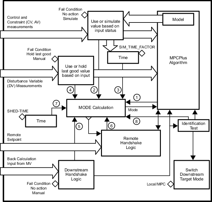
The conditions that impact mode are evaluated before executing the MODE calculation. These conditions are evaluated in the following order:
- No Model - If the process model has not been downloaded for this block, then the No Model flag is set. Otherwise this flag is cleared.
- Bad Control Input:
- If the status of one or more Control or Constraint parameters is Bad, Good Constant, or Uncertain (and the status option is configured to treat Uncertain as Bad) AND the Fail Condition for that input is Manual, then the Bad Control Input flag is set. Otherwise, the Bad Control Input Flag is cleared
- If the input is Bad, Uncertain (and treated as Bad) or Good Constant, then take the configured fail action.
- If Simulate is defined as the Fail Condition, or the input has a status of constant (analyzer or manual input) then the associated model value from the last execution is passed to the MPCPro algorithm as the measured input. A Simulate timer is set (if not already set). Reset the Simulate time if none of the Control inputs are being simulated.
- Simulate Too Long - The simulate timer is checked to see if it is set or cleared. If the Simulate timer exceeds the timeout limit based on time to steady state, then the Simulate Too Long flag is set. Otherwise, the Simulate Too Long flag is cleared.
- Bad Disturbance Input - If the status of one or more Disturbance parameters is Bad or Uncertain (and the status option is configured to treat Uncertain as Bad) AND the Fail Condition for that input is Manual, then the Bad Disturbance Input flag is set. Otherwise, the Bad Disturbance Input flag is cleared. If a Disturbance input is Bad and Hold Last Good is defined as the Fail Condition, then the input value used in the MPCPlus control is not updated.
- Bad Downstream - If no handshake has completed or the handshake associated with one or more of the Manipulated process inputs is incomplete (as a result of the back calculation inputs having a status of Bad or a status of Good Cascade Not Invited) and the associated Fail Condition for that input is Manual, then set the Bad Downstream flag. Otherwise, the Bad Downstream flag is cleared. If the handshake is incomplete and the Fail Condition is hold last good, then the last good back calculation input is passed as the current position of the MV to the MPCPlus algorithm.
- Remote Unavailable - If the target mode of the MPCPlus block is RCAS and the handshake with one or more of the RCAS inputs is not complete, then the Remote Unavailable flag is set. Otherwise, the Remote Unavailable flag is cleared.
- Remote Timeout - If the actual mode of the MPCPlus block is RCAS, then a remote timer is set (if not already set) for each RCAS input that has not been updated since the last execution. If any of the RCAS timers exceed the limit based on the time to steady state, then the Remote Timeout flag is set. If the actual mode of the block is not RCAS, then the remote timers are reset.
- Test Active - Handshake is complete with downstream loops that will be required for automated testing and process identification is ready to start. While testing is active, the mode of the MPCPlus block transitions to LO to indicate to an operator that one or more MPCPlus outputs are automatically adjusted.